Costruisci il tuo trasmettitore stereo FM compatto in grado di produrre audio con distorsione ultra bassa e segnali VHF precisi, utilizzando solo una semplice logica CMOS. Perfetto per imparare come funziona la stereofonia FM, questo strumento da laboratorio DIY ti consente di testare sintonizzatori, decodificatori e amplificatori con precisione di livello professionale.
Costruisci il tuo trasmettitore stereo FM compatto in grado di produrre audio con distorsione ultra bassa e segnali VHF precisi, utilizzando solo una semplice logica CMOS. Perfetto per imparare come funziona la stereofonia FM, questo strumento da laboratorio DIY ti consente di testare sintonizzatori, decodificatori e amplificatori con precisione di livello professionale.
The Circuit
The circuit was first presented by Jo Becker in Elektor June 2006. The test signal generator stands out for its precision and the clever way it creates waveforms using only standard HCMOS logic instead of special ICs. Driven by a 9.728 MHz crystal, it generates audio signals through counters and logic, with outputs switchable between a low-distortion tone and baseband signal. The FM oscillator runs freely but remains stable around 100 MHz, with coarse tuning via capacitor changes and fine adjustment of ±300 kHz. With up to 2 Vpp audio output and a 12 mV RF output into 50 Ω, it easily drives receivers for maximum signal-to-noise performance.
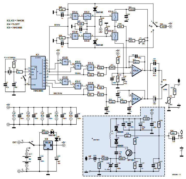
Circuit diagram of the stereo test transmitter.
When you refer to the schematic, the FM transmitter is the highlighted area around transistor T1. The remainder of the circuit produces the modulating signals, which are available at the audio output (via R15). An optional external modulating signal can be coupled in via C33 and R34, Becker explained.
The PCB
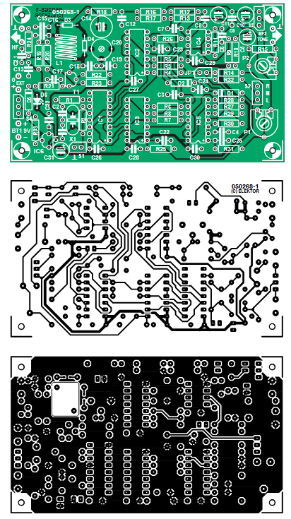
The PCB has a ground plane over the whole of the component side. The only coil (L1) should be mounted without a gap between it and the circuit board.
The double-sided PCB. Holes are not plated through.
"The current consumption of the test transmitter is only 12 mA and so a 9 V alkaline PP3-type battery should give several years of occasional use," Becker noted.
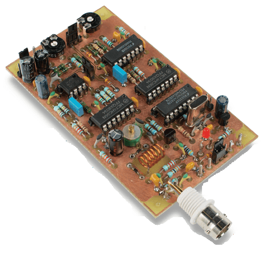
For occasional lab use, the circuit doesn’t require an enclosure. The switch connections (S1–S4) are routed to headers so simple jumpers can replace physical switches, and the output level control (P2) is implemented as an on-board trimmer. A BNC connector for the FM output can be soldered directly to the board near R24. This way, when used without a case, all components (apart from the battery) remain firmly fixed to the PCB.
Populated laboratory prototype board.
The Original FM Stereo Test Transmitter Project
The original article, “FM Stereo Test Transmitter: VHF FM and audio test signals,’” appeared in Elektor June 2006. You can read the article for free during the two-week period following the publication of this post. If you create a circuit of your own, please share it on the Elektor Labs platform!
Editor's Note: This article first appeared in 2006. Given the project’s age, some components or products might not be available, and the key design techniques might seem antiquated. However, we believe the project will inspire you to start new designs in the future.
Registrazione
Notifica tag: Iscriviti al tag Circuits & Circuit Design e riceverai un’e-mail non appena un nuovo contenuto a riguardo verrà pubblicato sul nostro sito web!


Commenti (0 commenti)