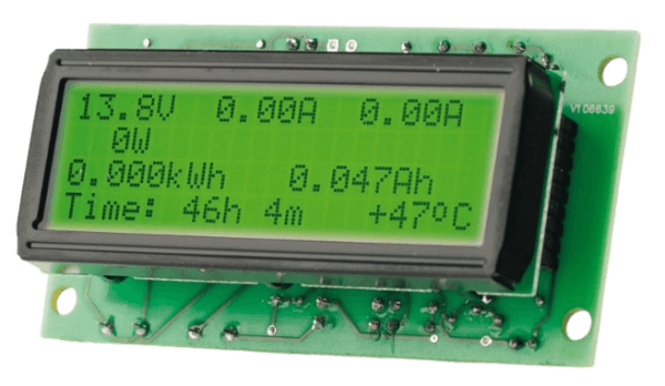
Ogni apparecchiatura di laboratorio necessita di letture di tensione e corrente. Ma se il display potesse fare di più? Questo wattmetro DC basato su microcontrollore mostra tensione, corrente, corrente di picco, potenza di uscita, carica in Ah ed energia in kWh.
With programmable timers, temperature monitoring, and firmware updates for future features, this DC power meter transforms a simple supply into a smart, versatile tool.
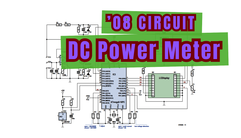
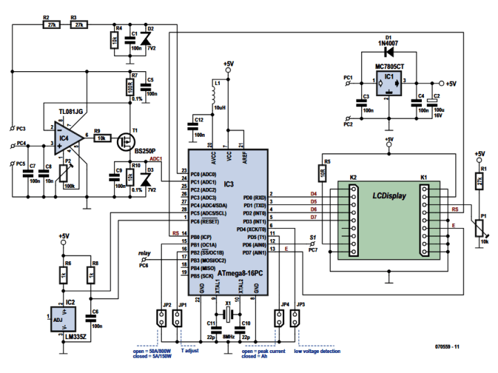
Versatile DC Power Meter Circuit
Oliver Micic presented this DC power meter design in the January 2008 edition of Elektor. The circuit featured an ATmega28-16PC. As no SMDs were used in the circuit, assembling it on the small PCB was fairly simple.
The instrument module used a DIP LCD with pin headers on both ends, which plugged into an instrument PCB equipped with socket headers. Since the design goal was to avoid SMD components, the circuit was kept as simple as possible so that all electronics could be placed beneath the LCD.
A microcontroller with a bit of signal conditioning circuitry.
“When you switch on the module the first time, you will be requested to calibrate the voltage if the accuracy of resistors R2–R4 (1% types) is not sufficient,” Micic explained.
“To do this, connect a multimeter to the output and a pushbutton switch to JP1, and then press this switch repeatedly until the value shown by the LCD matches the value shown by the multimeter. This should be done at 13.8 V with no load. After you have set the voltage, the calibration is accepted after 10 seconds and stored in the EEPROM. If you want to repeat this process, hold the push button pressed during switch-on until the corresponding message is shown on the LCD. Next, you have to adjust P2 for the current measurement (symmetry adjustment of opamp IC4). To do this, connect a load to the supply (or the battery), measure the current with a multimeter and adjust P2 for an equal reading on the LCD.”
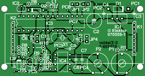
Component side of the prototype PCB.
Technical Data
Consider the key technical data for the DC power meter project:
Voltage range: 0–30 V
Maximum current: 5 A or 50 A
Peak current (Ip)
Power range: 1–999 W
Power measuring range (depending on JP1): 150 W / 800 W
Electrical power in kWh
Battery charge in Ah
Operating time in hours or minutes (in days after 1 week)
Bar graph display for power
Selected display option stored in EEPROM
Jumper-selectable Ah/Ip display; selection also possible during operation
LCD backlight
Optional temperature sensor with software calibration
Sandwich module (LCD and PCB)
Firmware versions available for 2 × 16 and 4 × 20 LCD modules
DC Power Meter display
The Original Project
The original article, “Versatile DC Power Meter,” appeared in Elektor January 2008. You can access the article for free during the two-week period following the publication of this post. If you develop a similar circuit, please consider sharing your progress on the Elektor Labs platform!
Editor's Note: This article first appeared in a 2008 edition of Elektor. Given the project’s age, some of the components or products might not be available, and the key design techniques might seem antiquated. However, we believe the design will inspire you to start new DIY electronics projects in the future.
Registrazione
Notifica tag: Iscriviti al tag Power & Energy e riceverai un’e-mail non appena un nuovo contenuto a riguardo verrà pubblicato sul nostro sito web!


Commenti (0 commenti)