Circuito: Milliohmetro
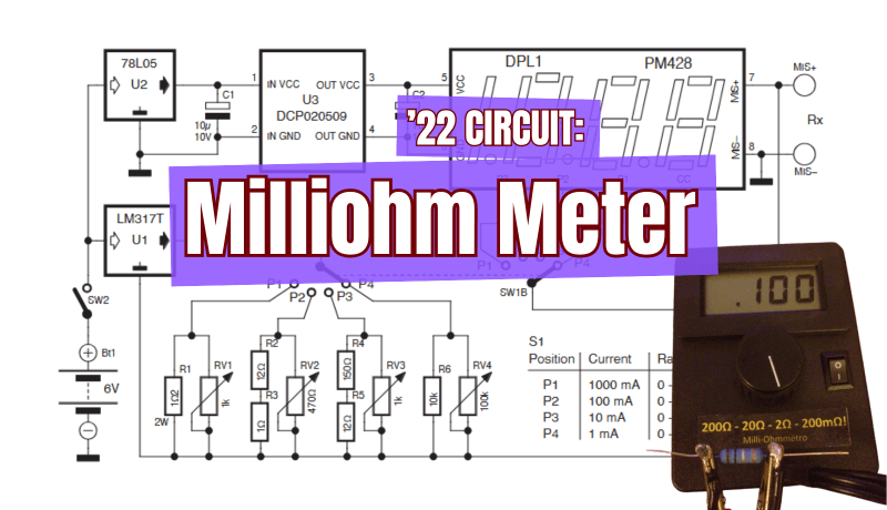
13 novembre 2025
su
su
Most multimeters struggle with accurately measuring very low resistances, but this precision instrument fills that gap. Designed to measure from 100 μΩ to 200 Ω across four ranges with 2% accuracy, it uses clever current regulation and isolated power circuitry to deliver reliable results.
The lower part of the circuit generates a constant current using an LM317 configured as a current source. The current is adjustable via a resistive network controlled by a four-position, two-deck rotary switch (SW1). A 2 W resistor is required for R1. The second deck of SW1 changes the display’s decimal point according to the selected measurement range.
The P1 range is the most sensitive, covering 0.1 to 200 mΩ, and delivers a 1 A test current to the device under test (DUT). Keep measurements brief on this range to conserve battery life, and always ensure the DUT can handle at least 1 A.
“First, calibrate the trimmers to obtain the current readings indicated in the table, measuring the DC current with a multimeter directly connected to the output terminals,” notes the designer, Stefano Purchiaroni. “To minimize the additional resistance of the probes, solder the measurement leads directly to the crocodile clips, to avoid adding the resistance of the current supply leads to the component to be measured. Note that the reading on the LCD will always show the sum of the resistance of the DUT and the resistance of the probes. The latter must be subtracted from the measurements carried out, especially in the P1 range.”
The accompanying images show one possible veroboard layout (yellow areas indicate interrupted tracks) and several photos of the prototype build.
Editor's Note: This article first appeared in a 2022 edition of Elektor. Given the project’s age, some of the components might not be available. However, we believe it will inspire you to start a creative project in the near future.
Milliohm Meter Circuit
This handy milliohm meter runs on four AAA lithium batteries, chosen for their low internal resistance. The top section of the circuit powers a standard 3.5-digit LCD panel meter (DPL1) with a 199.9 mV full-scale input range. Since this module needs an isolated 9-V supply, the circuit uses a linear voltage regulator (U2) to stabilize the battery pack at 5 V, which is then boosted to 9 V by an isolated DC-DC converter (U3, type DCP020509 from Texas Instruments). The converter’s input must not exceed 5.5 V, which is why a 78L05 regulator is included.
The P1 range is the most sensitive, covering 0.1 to 200 mΩ, and delivers a 1 A test current to the device under test (DUT). Keep measurements brief on this range to conserve battery life, and always ensure the DUT can handle at least 1 A.

“First, calibrate the trimmers to obtain the current readings indicated in the table, measuring the DC current with a multimeter directly connected to the output terminals,” notes the designer, Stefano Purchiaroni. “To minimize the additional resistance of the probes, solder the measurement leads directly to the crocodile clips, to avoid adding the resistance of the current supply leads to the component to be measured. Note that the reading on the LCD will always show the sum of the resistance of the DUT and the resistance of the probes. The latter must be subtracted from the measurements carried out, especially in the P1 range.”
The accompanying images show one possible veroboard layout (yellow areas indicate interrupted tracks) and several photos of the prototype build.

The Original Project
The original article, “Milliohm Meter,’” appeared in Elektor Summer Circuits 2022. You can read the article for free during the two-week period following the publication of this post. If you start working on design, please consider sharing your progress on the Elektor Labs platform!Editor's Note: This article first appeared in a 2022 edition of Elektor. Given the project’s age, some of the components might not be available. However, we believe it will inspire you to start a creative project in the near future.
Registrazione
Iscriviti per ricevere e-mail di avviso sui tag riguardanti Circuits & Circuit Design! Leggi l'articolo completo
Nascondi l'articolo completo

Discussione (0 nota(e))