
Progetti Arduino Controllati da Smartphone: Utilizza Bluetooth e Wi-Fi per la Comunicazione Wireless
su

To develop projects, we use components from the Elektor Universal Sensor Maker Kit together with the Arduino Uno development board. Unless specified otherwise, the projects developed are compatible with the Arduino Uno R3, the Arduino Uno R4 Minima, and the Arduino Uno R4 Wi-Fi.
Controlling the Arduino Uno Ports via Bluetooth Module
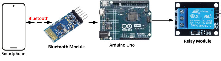
In this project, a Bluetooth module and a Relay module are connected to the Arduino Uno. The relay is controlled remotely from a smartphone via Bluetooth. The commands used are:
R=1# Activate the relay
R=0# Deactivate the relay
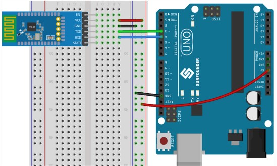
Figure 1 shows the block diagram of the project. The wiring diagram in Figure 2 illustrates how the Bluetooth module is connected to ports 3 and 4 of the Arduino Uno.
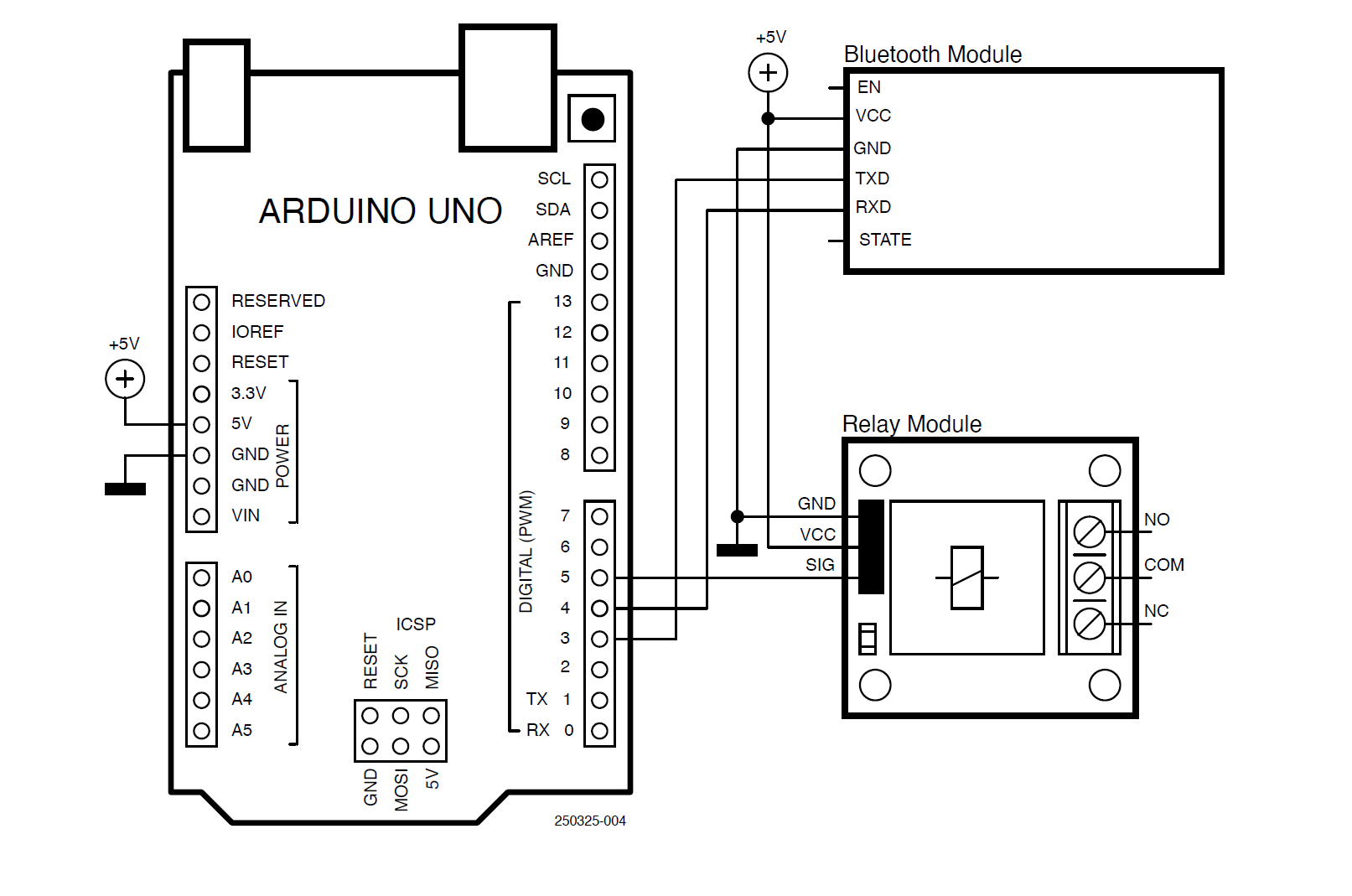
Listing 1 shows the program listing (Arduino_Bluetooth.c). The SoftwareSerial library is used in this program. The Bluetooth module’s TX and RX pins are connected to ports 3 and 4 of the Arduino Uno, respectively. The relay module is connected to port 5, configured as an output, and is deactivated at the start of the program. Inside the program loop, the program waits for data to be received from the Bluetooth module. The character # is used as the data terminator. If the received data is R=1, the relay is activated. If the received data is R=0, the relay is deactivated. Note that the terminator character is not part of the received data.
Listing 1: Controlling the Arduino using the Bluetooth module.
#include <SoftwareSerial.h>
const int BluetoothTXPin = 3; // TX pin
const int BluetoothRXPin = 4; // RX pin
const int Relay = 5; // Relay pin
String cmd;
SoftwareSerial BluetoothSerial(BluetoothTXPin, BluetoothRXPin);
void setup()
{
pinMode(Relay, OUTPUT); // Relay is output
digitalWrite(Relay, LOW); // Relay deactive
BluetoothSerial.begin(9600); // Bluetooth
}
void loop()
{
if(BluetoothSerial.available() > 0) // Data arrived?
{
cmd = BluetoothSerial.readStringUntil('#'); // Read the data
if(cmd == "R=1") // R=1?
{
digitalWrite(Relay, HIGH); // Relay ON
BluetoothSerial.println("Relay turned ON");
}
if(cmd == "R=0") // R=0?
{
digitalWrite(Relay, LOW); // Relay OFF
BluetoothSerial.println("Relay turned OFF");
}
}
}
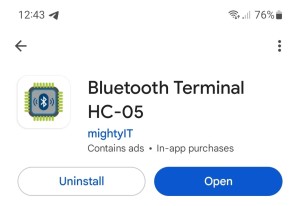
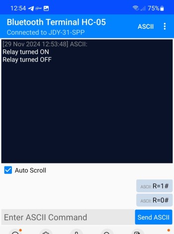
The project can be tested using a Bluetooth app on your smartphone. The author used the Bluetooth Terminal HC-05 app from mightyIT (Figure 4) on his Android smartphone.
- Construct the hardware and upload the program to your Arduino Uno.
- Turn on the Bluetooth and open the Bluetooth app on your smartphone.
- Click to SCAN for devices.
- The Arduino Uno Bluetooth module should appear as JDY-31-SPP. Click to select it.
- You may be asked to enter a pairing password. Enter 1234.
- Enter the command R=1#. You should hear the relay turn on, and the message Relay turned ON should be displayed on your smartphone.
- Enter the command R=0#. You should hear the relay turn off, and the message Relay turned OFF should be displayed on your smartphone.
Figure 5 shows the smartphone sending commands to the Arduino Uno.
Controlling the Arduino Uno Ports via Wi-Fi
In this project, an ESP8266 module is used to add Wi-Fi capability to the Arduino Uno board (assuming you are not using the Arduino Uno R4 Wi-Fi board). The project allows a relay connected to the Arduino Uno to be activated remotely over a Wi-Fi link using a smartphone. The valid commands are:
R=1# Relay on
R=0# Relay off
Figure 6 shows the project block diagram.

- Operating voltage: +3.3 V
- Interface: using simple AT commands over serial port/UART
- Integrated TCP/IP protocol stack. 802.11 b/g/n
- No external components required
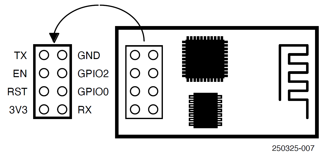
The ESP-01 communicates with the host processor through its TX and RX serial port pins. It is an 8-pin board, with the following pin configuration:
VCC: +3.3 V power supply
GND: Ground
GPIO0 (or IO1): I/O pin, must be connected to +3.3 V for normal operation
GPIO2 (or IO2): General purpose I/O pin
RST: Reset pin, must be connected to +3.3 V for normal operation
CH_PD (or EN): Enable pin, must be connected to +3.3 V for normal operation
TX: Serial output pin
RX: Serial input pin
ESP-01 pins are not standard breadboard-compatible, and an adapter is required if the board is to be attached to a breadboard. Some adapter boards also include a +5 V to +3.3 V converter chip so that +5 V can be directly connected to the device. The kit supplied with the book includes such an adapter, and you should plug your ESP-01 board into the adapter board.
The ESP-01 processor is operated with AT commands. Some commonly used AT commands for Wi-Fi connectivity include:
AT+RST - Reset ESP-01
AT+CWMODE - Set ESP-01 mode (in this case, Station mode)
AT+CWJAP - Set the Wi-Fi SSID name and password
AT+CPIMUX - Set connection mode (in this project, it is set to multiple connections)
AT+CIFSR - Return the IP address
AT+CIPSTART - Set TCP or UDP connection mode, destination IP address, and port number. UDP is used in this project with port 5000. The destination IP address is set to 0.0.0.0, allowing any device to send data as long as port 5000 is used. You can change this to the IP address of your smartphone to restrict access to it only.

Listing 2 shows the program listing (Arduino_wifi.c). At the beginning of the program, the TX and RX pins of the ESP-01 are assigned to software serial ports 2 and 3 of the Arduino Uno, and the relay is assigned to port 5 and is configured as an output. The function ConnectToWiFi() uses the AT commands to connect to the local Wi-Fi router. An important point to note is that the SSID and password of the router must be specified with the CWJAP command. The function then establishes a UDP communication protocol on port 5000.
Listing 2: Controlling the Arduino using the ESP8266 as Wi-Fi module.
#include <SoftwareSerial.h>
const int ESPTxPin = 2; // TX pin
const int ESPRxPin = 3; // RX pin
const int Relay = 5; // Relay port
String buf;
SoftwareSerial ESPSerial(ESPTxPin, ESPRxPin);
// This function connects to the local WiFi router using AT commands
void ConnectToWiFi()
{
ESPSerial.println("AT+RST");
delay(5000);
ESPSerial.println("AT+CWMODE=1");
delay(3000);
ESPSerial.println("AT+CWJAP=\"BTHub5-6SPN\",\"af4b5e6243\"");
delay(5000);
ESPSerial.println("AT+CIPMUX=0");
delay(3000);
ESPSerial.println("AT+CIPSTART=\"UDP\",\"0.0.0.0\",5000,5000,2");
delay(5000);
ESPSerial.println("AT+CIFSR");
delay(5000);
}
void setup()
{
pinMode(Relay, OUTPUT); // Relay is output
digitalWrite(Relay, LOW); // Relay deactive
ESPSerial.begin(115200); // ESP serial
ConnectToWiFi(); // Connect to WiFi
}
void loop()
{
if(ESPSerial.available()) // Data available?
{
buf = ESPSerial.readStringUntil('#'); // Read data
int i = buf.indexOf('R'); // Look for 'R'
if(i > 0) // i is index of R
{
if(buf[i] == 'R' && buf[i+1] == '=' && buf[i+2] == '1')
{
digitalWrite(Relay, HIGH);
}
if(buf[i] == 'R' && buf[i+1] == '=' && buf[i+2] == '0')
{
digitalWrite(Relay, LOW);
}
}
}
}
Inside the main program loop, the function ConnectToWiFi() is called to connect to the local Wi-Fi router. Then, the program waits to receive commands from the smartphone over the UDP port. Character R is looked for in the received data using the built-in function indexOf(). This function returns -1 if the required character is not found; otherwise, it returns the index where the required character is found. If the received command is R=1, the relay is turned on. If the received command is R=0, the relay is turned off.
Before starting the test, you should install a UDP app on your Android smartphone. There are many freely available UDP apps in the Play Store. The app used in this project is called UDP/TCP Widget by K.J.M, as shown in Figure 9.
- Construct the circuit.
- Download the program to your Arduino.
- Start the UDP/TCP Widget app on your smartphone.
- Click the gear symbol and set the protocol to UDP. Enter the IP address of your ESP-01 (e.g., 192.168.1.160 for the author’s ESP-01), and set the port to 5000 as shown in Figure 10.
- Click the MESSAGE menu item, select Text (UTF-8) as the format, and enter command R=1# to turn on the relay or R=0# to turn it off. Select LF\n as the Terminator.
- Click the red right arrow and then the SEND button to send the command to the Arduino Uno.
You can find the IP address of the ESP-01 by scanning all the devices on the local Wi-Fi router. For example, the Android app Who Uses My WiFi – Net Scanner by Phuongpn can show the IP addresses of all devices connected to your router.

Editor’s Note: This article (250325-01) appers in Elektor September/October 2025. It is an excerpt from the Elektor Universal Sensor Maker Kit. It was formatted and lightly edited to match Elektor Magazine’s conventions and page layout.
Questions About These Arduino Projects?
If you have questions or comments about these Arduino projects, email the author at d.ibrahim@btinternet.com or Elektor at editor@elektor.com.

Commenti (0 commenti)