
Introduzione a un Sensore Radar Moderno: Le Misurazioni del Tuo Radar Sono Accurate?
su
Let’s get started with the A121 radar sensor from Acconeer, a very powerful but not so easy-to-master sensor. Besides some background information, I provide a lot of tips for putting it to use!
The A121 radar sensor
Sensors are fascinating. Some time ago, while I was doing research to build a mailbox mail indicator, I came across an interesting video by Andreas Spiess that, among other things, mentioned a very powerful radar sensor, the A121 from the Swedish company Acconeer, costing about €12. This strongly intrigued me and made me want to give it a try! The manufacturer’s official development kit, the XE125, is quite expensive (around €120), but fortunately, SparkFun also offers a development board based on the same sensor for $50. This is better, and the price helps support a company that does a great job, with their modules and documentation, of making electronics accessible to engineers of all levels. The fact that SparkFun and Elektor are business partners did not influence my choice, and I am glad to have paid for this module with my own money. That said, let’s dive in!
Radar 101
While the general principle of a radar is to emit a radio signal toward a target and analyze the reflected signal, there are different types. In continuous wave (CW) radar, like the HB100 previously featured in Elektor or the similar CDM324, a constant frequency signal is transmitted and received simultaneously, allowing measurement of the target’s velocity through Doppler shift, but not its distance. Frequency-modulated continuous wave (FMCW) radar improves on this by continuously varying the transmitted signal’s frequency over time. As the wave takes time to travel to and from the target, at any given instant the received signal is a different frequency than the transmitted signal. By measuring the difference between those frequencies, the distance to the object can be computed.
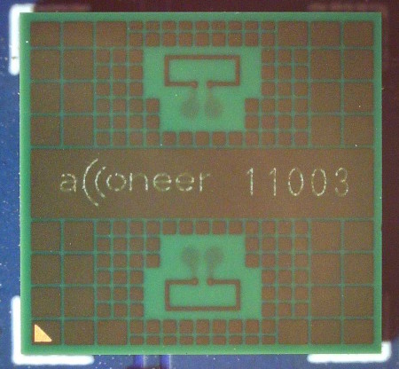
In contrast, Pulsed Radar transmit short bursts of signal at a single frequency and listens for echoes between pulses. Measuring the time t elapsed between transmission and reception of the reflected signal gives the measured distance d by the equation d = 1/2 × t × v, where v is the propagation speed of the wave, which depends on the material. The A121 (Figure 1) is a Pulsed Coherent Radar, coherent meaning that it is able to measure the phase of the received signal for even more precise measurement.
Hardware Overview
The A121 uses the 60 GHz band and offers a lot of features within a very small form factor (5.2 × 5.5 × 0.8 mm). It is fully integrated, with the baseband processor, RF front-end, and antenna in the same package, and a digital output via SPI. Internally, the A121 measures time differences with a resolution on the order of a picosecond, which provides excellent distance resolution, on the order of 0.1 mm (!). The maximum range is about 20 m. This is a very complex component; explaining it in detail would both be very hard, and go far beyond the scope of this article, but the manufacturer’s documentation (see here and here) is very good and abundant.
Acconeer suggests applications like distance measurement, proximity or presence detection, measuring velocity, tracking objects, robot navigation, etc. Thanks to its high resolution in distance mode, the A121 can also monitor vital life signs such as breathing and pulse rate. As the sensor outputs phase and amplitude of the received signal, it’s possible (by processing the data on a microcontroller connected to it) to detect and classify different materials, and recognize basic gestures. As other radar sensors, it’s immune to dust, variations of ambient light, etc.
All this is excellent, but on its own, this component is not very easy to discover and experiment with, for two reasons: first, this tiny package is a 50-ball BGA, which is not so easy to solder. Second, using the advanced features requires a lot of data processing through software, which represents a significant amount of work for anyone just considering trying out the component. To address this, Acconeer has a great solution.
The XM125 Module
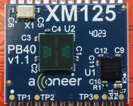
The Acconeer XM125 module (Figure 2) makes it much easier to explore the product. It is a small rectangular PCB measuring 18.6 mm × 15 mm, containing: the A121 sensor, a 24-MHz crystal required for its operation, a few resistors and capacitors, and finally an STM32L431CBY6 microcontroller from STMicroelectronics. All components are mounted on the top side, allowing the module to be soldered flat onto a Land Grid Array (LGA) footprint on your prototype PCB, using hot air or a soldering iron. Of the 28 pins with a 1.27-mm pitch (more accessible than BGA for us mortals), only a few are absolutely necessary; it would even be possible to solder wires directly for prototyping without a PCB.
The module is compact enough to be directly integrated into commercial products. It may function as a stand-alone unit, allowing customers to build their applications on top of the Acconeer software. Alternatively, it can be paired with an external microcontroller, communicating with the module using a register command protocol via a serial port or I²C.
A SparkFun Breakout Board
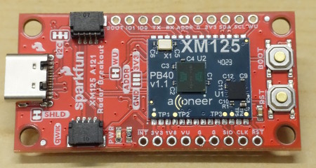
Integrating a microcontroller into the module was a smart choice. This way, Acconeer can offer downloadable firmware files that are already compiled and ready to be flashed onto the STM32L431, making it much easier to try out the sensor. SparkFun makes things even more convenient, with a PCB that includes the XM125, a CH340C USB-to-UART converter, a USB-C port, and the necessary voltage regulators, as can be seen on Figure 3. Two Qwiic connectors allow the module to be linked via I²C to other SparkFun boards.
This breakout board is simply intended to make connections easier; it does not include an additional microcontroller. SparkFun suggests to use the provided binaries as-is for the STM32L431, and to develop your own application on an external microcontroller, for example an ESP32 on an extra board, communicating with the XM125 via I²C. For more advanced users, or those familiar with STM32 products, it is also possible to do without an external microcontroller and to fully develop your project on the provided STM32L431.
Software
Acconeer offers many options in terms of software. For the XM125, a Software Development Kit (SDK) is provided and contains source code and compiled files, directly transferable to the onboard STM32L431, for many example applications (distance measurement, speed, presence detection, etc.). For those planning to use the A121 sensor in a fully custom project without the XM125 module, other SDKs are also available in different variants (Keil, ARM-GCC, IAR, etc.) for ARM Cortex M7, M4, M33, M0 platforms. A dedicated PDF guide is available for each case.
Special mention goes to the Exploration Tool published by Acconeer, this time on GitHub. Fully programmed in Python, it provides a useful graphical interface on PC (Windows or Linux) to evaluate the A121, modify its parameters, and stream live measurements to the PC. Let’s take a closer look.
The Acconeer Exploration Tool
For those who have never installed the Python interpreter on their PC, now is the time to do so. The Exploration Tool is installed using the pip package manager. However, some Linux distributions (like Mint, which I recently tried) strongly advise against using pip on the system’s Python interpreter, as there’s apparently a risk of messing with packages used by the system itself. In these cases, it is recommended to run pip inside a virtual environment. It may also be worth doing the same on Windows to keep control over the packages you install or uninstall for each project. I used PyCharm, which works well on both Windows and Linux.
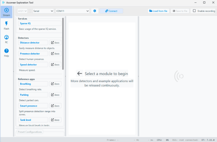
In the terminal (of PyCharm or your system), install the Exploration Tool with the command python -m pip install --upgrade acconeer-exptool[app] and, once all packages are installed, launch the GUI interface with the command python -m acconeer.exptool.app. The Exploration Tool also supports the predecessor of the A121, the A111. Click the left panel to open the A121 version. The main window that opens is shown in Figure 4.
Firmware Download
Just as each specific situation (distance, speed, presence measurement, etc.) has its own optimized firmware available in binary format, the Exploration Tool also needs a specific firmware, called the Exploration Server. To start, create an account here. Then download the Exploration Server firmware here and unzip the ZIP file.
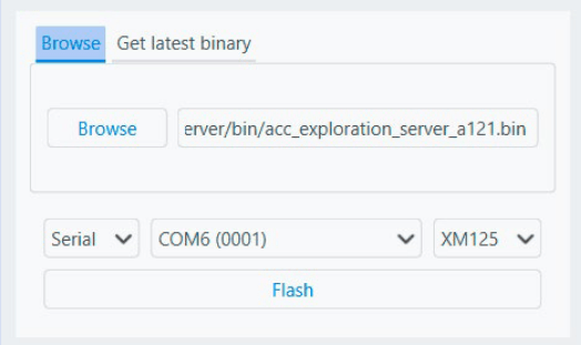
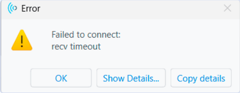
The Exploration Tool contains four distinct sections: Stream, Flash, Resource Calculator (RC), and Help. These are accessible through buttons on the left. First, open the Flash page (Figure 5). In principle, it is possible to directly download the latest firmware version under the Get Latest Binary tab. As of the time of writing, a bug seems to exist: the firmware acconeer_xc120_exploration_server_a121-v1_10_0.bin downloaded via the Exploration Tool does not work properly. Although flashing seems normal, trying to connect to the module afterward results in a connection failure (Figure 6). Among other minor issues, the link provided by the Exploration Tool to create a Developer account returns a 404 error. Use this instead.
To work around the firmware bug, select the Browse tab and manually select the firmware file from the ZIP you downloaded earlier. Choose Serial, then the correct serial port (on Windows, you can check the port number in the Device Manager when plugging in the module), then XM125. Finally, click Flash and follow the on-screen instructions: press the Boot button, then the Reset button while keeping Boot pressed, release Reset, and then release Boot. I recommend not doing this sequence too quickly; leave at least a third to half a second between each press. Flashing should complete normally.
First Tests
Now, click on the Advanced Settings button (to the left of Connect in the top bar) and type 115200 in the Baudrate field. Close Advanced Settings and click Connect. Congratulations, your module is connected!
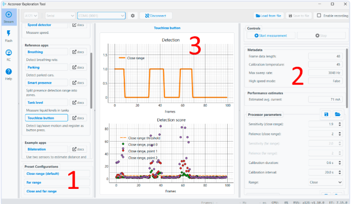
You can now try out the functionalities of the Exploration Tool. The different functions are listed on the left panel: Sparse IQ, Distance Detector, Presence Detector, Speed Detector, etc. For each application, three display areas are used (Figure 7): Preset Configurations at the bottom of the left panel (label 1 in the figure), detailed settings on the right panel (2), and measurement results in the center (3). Each application must be started with the Start measurement button. Feel free to explore the various demo applications. The Sparse IQ page displays the raw data output from the sensor, in the form of the amplitude and phase of the received signals, represented as complex numbers. It may be a bit difficult to interpret these values by eye. Although it is listed first, it is not the most fun. Presence Detector and Touchless Button are easier to understand.
Make It Faster!
After a few tests, I realized that the graph display was not very smooth: data arrives in bursts. While some applications like Touchless Button work fairly well, there are five-second pauses between data bursts and refreshing of the curves in Sparse IQ, Presence Detector, and others. It’s a bit frustrating considering the sensor’s speed and all the effort Acconeer put into creating a great software tool.
It turns out neither Acconeer nor the sensor is to blame. It’s an unfortunate coincidence that SparkFun hasn’t corrected yet. The CH340C from WCH, a very popular USB-to-UART converter used in several SparkFun boards, was used here again, which is logical for SparkFun. Unfortunately, it does not fully support Hardware Flow Control, even though it has RTS and CTS pins (required by the XM125). The CH340C datasheet version 1D is vague about this: “The USB to serial interface is only compatible with the application layer, not totally”. Later, the version 3B of the same document says: “For one-directional 1 Mbps and above, or bi-directional 500 kbps and above, we recommended to use CH343, and enable automatic hardware flow control.”
What a pity! Here, the XM125 and Exploration Tool need Hardware Flow Control to optimize data throughput. On the XE125 (official Acconeer dev kit), a Silicon Labs CP2105 is used instead. Maybe SparkFun will release a Revision 2? For now, SparkFun’s Hookup Guide notes: “Note: The Acconeer Exploration Tool may run slower than expected when using the SparkFun XM125 Pulsed Coherent Radar Sensor.” Acconeer’s Exploration Tool FAQ also confirms this.
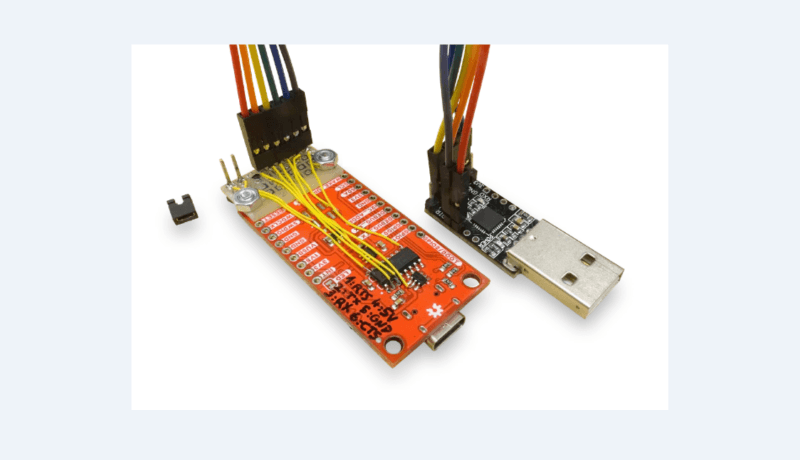
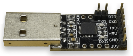
I didn’t have a CP2105-based module on hand to try; the CP2105 Friend from Adafruit would be ideal but was out of stock when writing. However, the CP2102 and CP2104 are quite similar and worth trying. They are used in many products – I had several gadgets on hand using them – but RTS and CTS pins are not always accessible. Digging through my inventory, I found a USB-serial adapter with a CP2102 where the necessary pins are exposed (Figure 8). When buying, check the available pins carefully in the photos or documentation.
As you’re not supposed to use a different USB to UART converter, there is no easy access to the primary TX, RX, CTS, and RTS signals; those are directly routed from the XM125 to the CH340C. The DEBUG_TX and DEBUG_RX pins on the side of the module are connected to the second serial port of the XM125, which is used for debugging only. This required some adaptation (Figure 9).
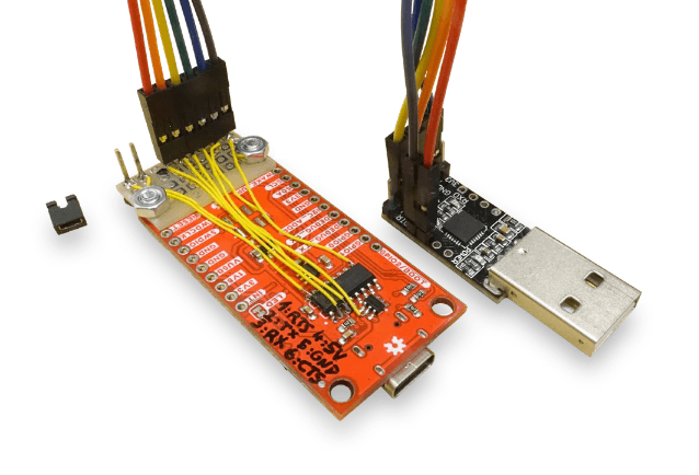
A small piece of perfboard was added to the sensor’s back side, and a pin header was wired to the corresponding pins of the CH340 using thin wire. If you attempt this, pins TX, RX, CTS, and RTS are pins 2, 3, 9, and 14 on the CH340C, respectively. You can also solder directly onto the XM125 pads on the front side. To disable the CH340C, its VCC pin (pin 16) must be disconnected, either by cutting the trace near the pin or carefully lifting the pin and removing solder. I added a jumper to make this reversible. Two extra wires (+5 V and GND) were also routed to the pin header to eliminate the original USB-C cable.
To use the CP210x instead of the CH340, simply change the COM port number in the Exploration Tool. In my case, the CP2102 worked properly, and the graphs now refresh continuously, between 2 and 20 times per second depending on the application. Much better! Another module based on the FT232RL by FTDI worked as well, but was slightly slower.
A Solution Looking for a Problem
The Presence Detector illustrates how the radar’s sensitivity to micro-movements gives an advantage over other types of sensors. I tried sitting perfectly still a few meters away from the sensor: no matter what, my tiny involuntary movements were detected by the A121, and the Exploration Tool clearly indicated I was always present, which is reassuring in case of an existential crisis. On the other hand, the Passive Infrared (PIR) sensor placed at the same distance ignored me after a few seconds if I stayed still. More interesting applications include remote vibration measurement of machines, or non-invasively monitoring people’s breathing. I tried that (see Figure 10), but there seems to be something wrong: During the test, I was calm and breathing much more slowly than what is shown. Moreover, the indication in bpm (breaths per minute) does not match the curve either. I will investigate and keep you informed in our Err-lectronics section if I find the bug. Personally, I haven’t yet found a direct use for the sensor at home, but studying it in detail is still a very satisfactory process. Feel free to email me your ideas or suggestions!

Going Further
It is recommended to tinker with the various settings of the Exploration Tool for yourself! Also have a look at the Resource Calculator panel, which provides estimates (not measurements) of the module’s power consumption based on the settings. Also check out SparkFun’s Hookup Guide, which offers an Arduino library that you can use on an external microcontroller of your choice, to help you communicate with the XM125 in Presence and Distance modes, through I²C. I encourage reading Acconeer’s documentation for a detailed understanding, and for the brave, taking a look at the source files. To develop your own application, you can also install STM32CubeIDE and build upon the Acconeer SDK with the STM32L431.
Do I recommend the SparkFun XM125 module? Hard to say. On paper, it’s great to have the same kind of functionality as the official Acconeer kit, at 40% of the price. If you mainly use the XM125 in Presence or Distance mode and, like SparkFun, mainly use the XM125 through its I²C interface, then the CH340C’s slowness doesn’t really matter. For those who want a smoother experience with the Exploration Tool and save some money, buying the XM125 alone, a separate USB-UART converter, and making a simple adapter PCB would be a better option. Have fun!
Editor's Note: This article (250167-01) about the radar sensor appears in Elektor July/August 2025.
Questions About the Radar Sensor?
Do you have questions about the radar sensor or comments about this article? Email the author at jean-francois.simon@elektor.com, or contact Elektor at editor@elektor.com.

Commenti (0 commenti)