
ESP-ROLL: Build a Spherical Self-balancing Robot with ESP32 Camera!
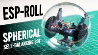
Build the ESP-ROLL - an ESP32 Self-balancing Ball Robot with Phone Control and FPV Cam that Rolls Smoothly over almost Any Surface!
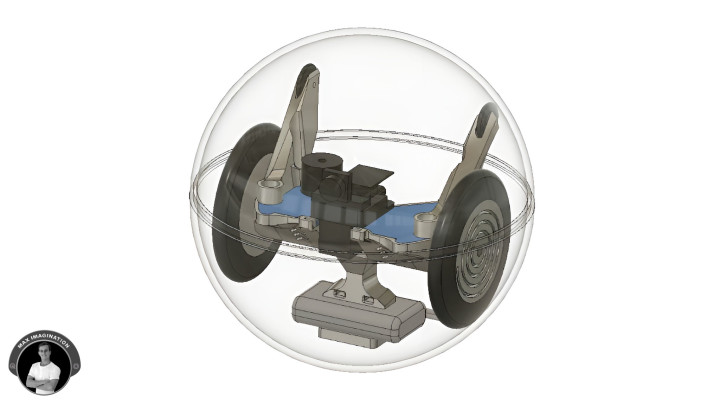
The ESP-ROLL is a small, home-built spherical robot that rolls inside a transparent ornament ball - great for entertaining pets, exploring under furniture, or showing off to friends. It glides across tile, carpet, grass, and even sand without sensors or external wheels. Powered by an ESP32 camera, it offers WiFi control, live FPV video, and runs on a simple 1S battery. With a 3D-printed chassis and clear ornament shell, it’s fun to build and easy to customize.
This guide covers everything you need - from wiring and 3D printing to assembly and programming - so you can build your own one in a weekend.
Grab your tools and let’s ‘roll’!
1. Gathering Parts and Resources
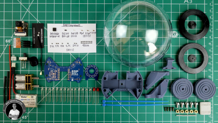
To bring the ESP-ROLL to life, we’ll need parts such as a lithium battery, geared motors, wire, power connectors, slide switch, buzzer, LEDs, surface mount components for controlling peripherals like motors and lights, a XIAO ESP32S3 Sense Camera with its accessories, main board and ring light PCBs, metal hardware, weights, zip ties, PLA and TPU for the 3D printed parts, and the shells of a transparent plastic ornament.
Here’s the full parts list with links:
- $13-24 - (x1) XIAO ESP32S3 Sense w/ antenna - https://amzn.to/4kkQnsQ / https://www.seeedstudio.com/XIAO-ESP32S3-Sense-p-5639.html?utm_source=youtube&utm_medium=MaxImagination&utm_campaign=ESPRoll
- $14 - (x2) 400RPM Micro metal geared motor - https://amzn.to/4kkQlRK
- $0.8 - DRV8833 Dual motor driver - https://amzn.to/4kGBv7J / https://amzn.to/43CUd9z
- $0.1 - (x1) SI2300 N MOSFET - https://amzn.to/4kYu1NK
- $0.05 - (x1) Red 0805 SMD LED - https://amzn.to/3SCIfrr
- $0.03 - Capacitors SMD 0805 - https://amzn.to/3Htm4S5
- (x1) 10uF
- (x1) 2.2uF
- (x1) 0.01uF
- $0.15 - Resistors SMD 0805 - https://amzn.to/4kzlPUj
- (x14) 150Ω
- (x2) 240Ω
- (x1) 4.7KΩ
- (x1) 10KΩ
- (x2) 47KΩ
- (x1) 51KΩ
- $3 - 3.7V 200-450mAh LiPo cell (Battery) - https://amzn.to/3StvYFz
- $0.3 - 3mm LEDs: Found in kit - https://amzn.to/4mGnfO3
- (x14) White
- (x2) Red
- $0.7 - (x1) 5V Active Buzzer - https://amzn.to/43mOJAU
- $0.9 - (x1) SS12F17 Micro Slide switch - https://amzn.to/4jFvYxo
- $0.12 - JST Battery connector - https://amzn.to/43kd2iO
- $0.1 - 28AWG Wire (15-20mm L) - https://amzn.to/4ee4RID
- $2 - (x1) 60+ gram weight - https://amzn.to/43AdJ6s
- $1.6 - (x1) 100mm Ornament Ball - https://amzn.to/3Ffq9Zy
- $0.25 - (x5) M3 Threaded Insert - https://amzn.to/3ZqV7EU
- $0.1 - (x5) M3 Screw (6mm) - https://amzn.to/45hqSUy
- $0.2 - (x4) M1.6 Screw (5mm L) - https://amzn.to/3Tr9eX6
- $N/A - 1.5mm Steel Wire (2 short pieces) - https://amzn.to/4jO5Dgv
- $0.05 - Small Zip Ties - https://amzn.to/3FXtmNu
- $0.4 (~23g) PLA Filament (Grey) - https://amzn.to/4kCETkn
- $0.2 (~7g) TPU Filament (Black) - https://amzn.to/43YGABL
- $13.1 - PCBs and Stencil - Order from JLCPCB
Total parts Cost: ~$62 USD (As of June 2025 excluding shipping and 3D model cost).
As an Amazon Associate, I earn from qualifying purchases with no added cost to you.
All the files - Code, Schematics, and PCB Gerbers are linked here:
Project Files - (PCB Gerbers, Schematic, and RTR Code)*
3D model/design of ESP-ROLL’s Frame (STLs): https://cults3d.com/en/3d-model/game/esp-roll-an-esp32-spherical-robot-with-camera-rc-ball-bot-3d-design-stl-fil-e83bfe979989d6ad6f66
Up-to-date Code (GitHub Repo Credits to ‘s60sc’): https://github.com/s60sc/ESP32-CAM_MJPEG2SD
ESP32-CAM Guide Video - In-depth Code/App Setup Guide: https://youtu.be/k_PJLkfqDuI
Software - Arduino IDE: https://www.arduino.cc/en/software/
2. Designing the PCB: The Electronic Backbone of the ESP-ROLL
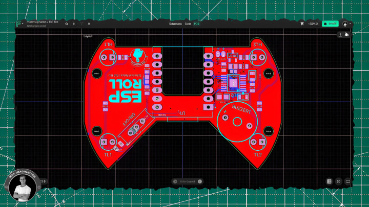
Tutorial aside, let me take you through you how I designed the PCB - what ties everything together inside the ESP-ROLL spherical robot, and designing it was a key part of this project. I began by placing all the parts: the XIAO ESP32S3 camera module, DRV8833 motor driver IC, passive components, and connectors. One challenge was sorting through a sea of conflicting motor driver schematics online. Fortunately, with some help from suggestions from Flux’s AI Copilot, I found the correct wiring for the chip, which saved time and gave me confidence in the design.
I also reached out to the GitHub author of the code I’m using to ask about adding a buzzer for low battery alerts. Thanks to their guidance, I integrated the buzzer, a voltage divider for battery monitoring, and a MOSFET to control the head and tail lights. I had considered a fancier latching power circuit with a pushbutton, but after testing a few ideas, I kept it simple with a reliable sliding switch.
Once the schematic was done, I shaped the custom board outline, positioned the components to fit the compact space, and added mounting holes and connector pads. After routing the traces and applying copper fills, I ran an AI design review to catch and correct a few small issues. A bit of branding was added, and the 2-layer PCB for the robot was complete and ready for manufacturing.
Curious what software I used to design the PCB? You can check out Flux here: https://www.flux.ai/signup?utm_source=influencer&utm_medium=organic_social&utm_campaign=MaxImagination2
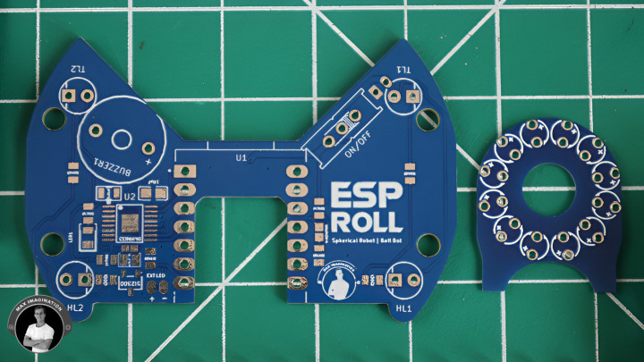
3. ESP-ROLL Schematic and PCB Gerbers
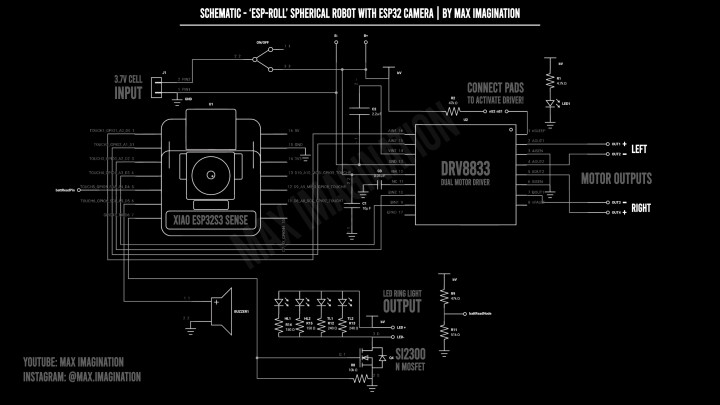
Also linked in the project files folder - at the start of this blog - are the schematic and Gerber files for both PCBs, which I’m providing to you for free and you can refer to at any time.
That includes a second board I designed: an LED ring light that wraps around the camera to act as a mini spotlight.
4. Ordering PCBs
Once you’ve downloaded the two PCB Gerber files, you’ll need to outsource manufacturing to a service like JLCPCB, who provide affordable, reliable boards for DIY projects like this.
Let me take you through their easy ordering process with these PCBs:
Head to their site and upload the Gerber ZIP files to get an instant quote for the ESP-ROLL’s PCBs. For the specs, set both boards to 2 layers. Choose how many copies you want.
Set the main board’s thickness to 1.6mm, and the ring light board to 1.0mm. Pick your favorite board color, and enable “Remove Mark” which removes the order number to keep your PCBs clean.
Leave the rest of the options as-is.
Then, scroll down and enable the PCB stencil option only for the main board if you wish to make soldering easier, which includes small surface-mount parts like the motor driver IC - those are tricky to solder by hand.
Set the stencil size to 80×50mm, and select the top side only.
Add both PCBs to your cart, making sure the main board includes the stencil, then check out.
You’ll be able to track the order from their fast 24-hour manufacturing through to shipping.
Mine arrived in just a few days - you should receive 5 boards (or other selected quantity) of each design, plus 1 stencil for the main one.
JLCPCB manufactures 1–8 layer boards starting at just $2, and their quality standards are top-tier.
Sign up to JLCPCB, get $70 in new user coupons and get the boards made here: https://jlcpcb.com/?from=MaxImagination
5. Assembling PCBs
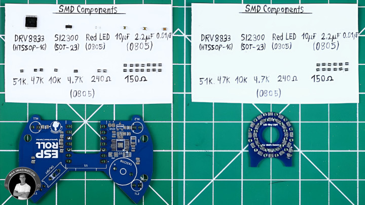
Once you have the PCBs, let’s move onto assembling them - starting with applying solder paste to each of the pads of the main board using its PCB stencil.
We’ll surround the board with some perf boards of the same height and tape them down. Aligning the stencil over the board, we’ll tape that down, apply a blob of solder paste and spread it over. We’ll carefully remove it, revealing the coated pads. Let’s do the same for the LED ring light PCB, only without a stencil as each pad is large enough to cover with the solder paste syringe alone.
Now, let’s pick and place the main board’s surface-mounted components - the resistors for the tail and headlights, the battery-measuring voltage divider’s resistors, power LED resistor, motor driver pullup resistor, MOSFET pull-down resistor, capacitors for the motor driver, a red power LED, MOSFET, and the Dual motor driver IC. If you have trouble finding this exact motor driver chip (DRV8833 in HTSSOP-16 package), consider salvaging it - reusing the driver and its surrounding components from its modular form.
For the ring light PCB, the only SMD components are the current-limiting resistors for each LED.
From here, we can place each board onto a hotplate (alternatively - use a hot air gun) and watch as the components melt into place while correcting those that get misaligned. If the chip’s pins get shorted with excess solder, simply swiping between them with a soldering iron can help clean them up.
6. Installing the Ball Bot’s Brain: XIAO ESP32S3 Sense
Next up, let’s install the brain of the whole spherical robot - the XIAO ESP32S3 Sense from Seeed Studio.
This tiny dev board is the camera-equipped version of the same microcontroller (XIAO ESP32S3) I used in my ESP-FLY drone project.
I designed the project’s PCB so it slots right on top using the castellated holes. It sits flat like that - and with a bit of soldering tin across the sides, it locks into place and connects to the circuit.
I chose this board because it packs a lot into a tiny footprint: built-in Wi-Fi for low-latency phone control, a 2MP camera for FPV video, a microphone, and even an SD card slot for recording videos you can play back later. It also runs directly off a 1-cell battery and handles charging - no extra circuitry needed.
Once it’s soldered, we can flip the board over and wire the battery pads on the bottom of the XIAO to the PCB which holds the battery connector.
This board is compact, low-power, and saves space - perfect when everything needs to fit inside a sphere. Find Seeed Studio’s XIAO ESP32S3 Sense linked here: https://www.seeedstudio.com/XIAO-ESP32S3-Sense-p-5639.html?utm_source=youtube&utm_medium=MaxImagination&utm_campaign=ESPRoll
7. Soldering Through-hole Components
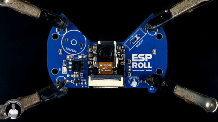
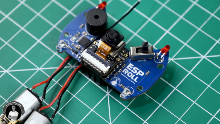
Now, let’s install the through-hole (THT) components - starting with the SPDT slide switch for controlling power to the board, a 5V active buzzer for motion detection and low-battery alerts, 3mm white and red LEDs for the robot’s head and tail lights - bent 90 degrees so they point outward when in place. We’ll also insert a JST battery connector and solder all of these components followed by trimming the protruding pins flush.
Then, we can hook up the motors to the bottom of the board with some 28 AWG wire. I’ve added markings to show the correct polarity and which side each motor belongs to. While we’re on the topic of motors, you mustn't forget to solder-bridge the two pads beside the motor driver IC or else the chip will not run - this pulls high a sleep pin (DRV8833’s nSLEEP pin). The voltage divider pads also need to get bridged to enable battery voltage monitoring.
With the XIAO, came an included heatsink which we’ll stick onto the bottom of the microcontroller to keep it cool - using the space I created for it in the design of the main PCB. Without it, the camera would get as hot as 70 or more degrees celsius, but with the heatsink, it runs at 50 to no more than 60 degrees, keeping it running optimally.
Another part that comes included with the ESP32 dev board was the antenna which we’ll modify by desoldering the flex PCB part of it, striping a section of the coaxial cable enamel, revealing the stranded wire shielding which we’ll trip off, exposing the insulated bit of wire that we’ll keep as the antenna. From my experience, this actually improves the signal.
We’ll clip on our customized antenna to the XIAO’s U.FL connector and clip back on the camera module.
For you the reader, now would be a good time to load the firmware as this will allow you to make sure the whole circuit works before putting everything into the casing - however, I will cover the code part later in the blog.
8. 3D Design
Let’s go through how I designed the ESP-ROLL in the CAD software called Autodesk Fusion.
I started by making a virtual sphere like the ornament shell the ESP-ROLL will sit in, took measurements of each and every single component and modeled them in Fusion, did the maths to end up with how each one should sit which is what helped me create PCB shape. Then, I was able to model around it - creating the enclosure and supporting parts like the weight holder and caster wheel arms. From there, I designed the wheels of the correct diameter and added some finer details such as the branding, symbols, mounts for certain components, and color.
To 3D print or tweak your own ball bot to your liking, the STLs, modifiable files, and all the details are listed on Cults 3D: https://cults3d.com/en/3d-model/game/esp-roll-an-fpv-esp32-spherical-robot-rc-ball-bot-3d-design-stl-files
9. 3D Printing
Next, let’s print the structural parts and wheels of the ESP-ROLL based on the design linked above - I’ll go with dark gray PLA filament for the first batch and TPU - the rubbery filament for the second batch where we 3D print the tires - giving the ball bot better grip.
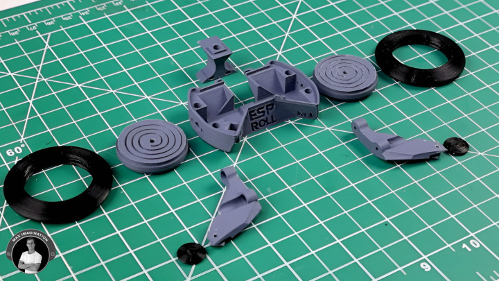
With the PLA and TPU parts 3D printed out, we remove supports and clean them up, leaving us with the finished 3D printed parts:
With the PLA and TPU parts 3D printed out, we remove supports and clean them up, leaving us with the finished 3D printed parts:
- Body Shell (PLA)
- Battery/Weight Holder (PLA)
- Left and Right Caster Arms (PLA)
- Left and Right Wheel Hubs (PLA)
- Tires (TPU)
- Caster Wheels (TPU)
3D Printing Settings for both PLA and TPU:
Layer Height: 0.12mm
Infill Density: 15%
Layer Height: 0.12mm
Infill Density: 15%
Supports: Yes
Print Speed: Desired speed for PLA | 20-40mm/s for TPU
Nozzle Temp: 200–220°C for PLA | 215-230°C for TPU
Bed Temp: 60°C
Cooling: On
Additional Print Info:
Materials:
- PLA/ePLA (1.75mm) – https://amzn.to/4kCETkn
- TPU (1.75mm) - https://amzn.to/43YGABL
- Material Usage - Internal parts: ~30g
- Material Usage - Sphere shells (Resin 3D printed - clear): ~90g
Sphere shells can be bought as transparent plastic ornament balls (preferred option) or even resin 3D printed.
Print Time: ~3.5 to 7 hours. For this project, I used an Elegoo Neptune 4 Plus.
10. Assembling Parts
To mount the board (Assembled PCB) and weights, we’ll need to install 5 of M3 threaded inserts - 4 into the body shell and 1 into the battery/weight holder.
Before installing motors, we must secure the weight holder into the bottom of the main body with the shortest possible M3 screw.
Then, we need to add strips of electrical tape as insulation on the motors to prevent them from shorting the pins on the board - only then can we shove them in and route the wires in such a way so that the main board can be pushed into place. Afterward, we’ll secure each motor with a couple of M1.6 screws 5 mm in length.
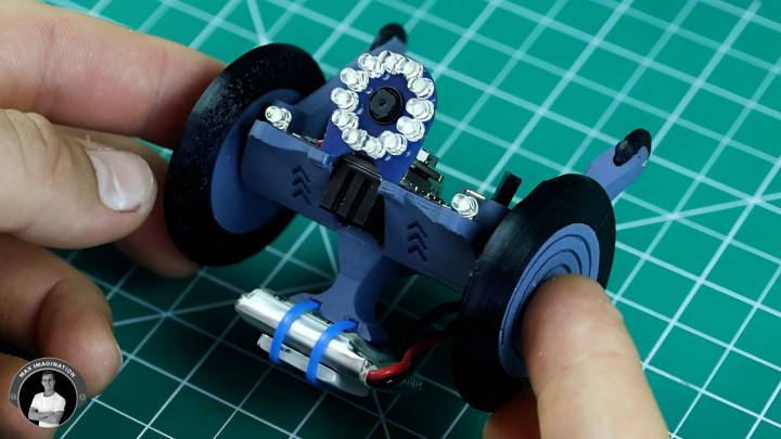
Now, let’s assemble the caster wheel arms - each gets a tiny, 3D printed TPU wheel inserted with a short piece of 1.5 mm steel wire as the pin that it rotates around. We’ll secure each arm with a couple of 6 mm-long M3 screws into the body of the bot. The wheels should rotate smoothly and work to support the bot from wobbling too much inside the ball.
Let’s go ahead, push in and solder twelve 3 mm LEDs into the ring light PCB with its SMD resistors already in place. We’ll trim away the excess pins and hook it up to the bot via a couple of wires to power it - connecting to the external LED pads designed for the ring light. Then, we can super glue it in place and insert the camera - making it protrude through the hole.
To come up with the wheels, we’ll mount the TPU tires onto the PLA wheel hubs with a perfect fit and then simply push them onto the motor shafts without any glue to leave room for the robot’s height adjustment within the ball later (Adjust the gap between the robot and bottom of the ball by sliding the wheels further onto or off the motor shafts).
Attaching the battery is as simple as lacing through a couple of small zip ties around it through the weight holder’s holes and also adding the weight of your choice - I am using a quarter-ounce or 7 gram weight to start with. Then we can plug the battery into the connector at the rear.
11. Adding Finishing Touches
We’ll use something like a toothpick and a marker to color in the debossed text and symbols around the ball bot.
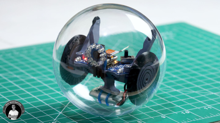
For the transparent plastic ball this robot will sit in, we’ll use one of those fillable clear ornaments.
Unpacking them, each ball comes in two halves you simply push together with a tight fit to form the ball. However, one thing is in the way that has to go and that is the tabs which form the loop for hanging the ornament. Now, the ball can roll without running into a knob.
To use the ball bot, just switch it on and close the shells around it to complete the spherical form.
12. Programming The ESP-ROLL
Alright, let’s program the robot!
We’ll be using a code called ESP32-CAM_MJPEG2SD from GitHub author “s60sc”. It’s a motion-capture web application for ESP32 cameras that I’ve used for DIY security cameras and RC cars in the past. Its primary feature is image-based motion detection which is how it triggers video recording, accepts a whole host of different sensors and peripherals such as a motor driver used with the remote control capability for vehicles we’ll be using primarily, and is even machine learning capable for detecting specific objects - if you train it.
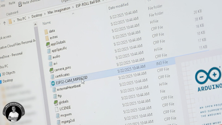
So you’ll want to head to this repository and download the zip file for the code: https://github.com/s60sc/ESP32-CAM_MJPEG2SD
Unzip it in its location. Then, rename the folder, removing “-master” from its name. Open the “.ino” file, loading the Arduino IDE - you should see all the surrounding files appear as well in their own tabs.
Go to the “appGlobals” header file and in the board selection section, comment-out all boards except for the XIAO ESP32S3 that we’re using. Scroll down a bit more and set “INCLUDE_PERIPH” to true and do the same for “INCLUDE_MCPWM” which enables the driving of motors.
Now, go to the Peripherals file, in the section for battery monitoring, under the battery task function - type “buzzerAlert(true);” under line 309 to ensure the buzzer beeps when the battery’s voltage drops below a set minimum threshold. That’s all you need to worry about changing in the code.
We can then connect up the ESP-ROLL to our computer and check we have the correct board info set under tools (The only details that need to be changed):
- Ensuring XIAO ESP32S3 is selected as the board.
- USB CDC on boot should be enabled.
- Select “Default with spiffs (3MB APP/1.5MB SPIFFS)” as the Partition Scheme.
- Enable PSRAM “OPI PSRAM”.
- Select the COM port the XIAO ESP32S3 is connected to.
Then, we can hit upload and wait a couple of minutes for the code to be flashed to the ESP-ROLL.
From here, we’ll need to take a microSD card, plug it in, and copy/paste the data folder (which came included with the code) to the card which is for storing your configuration parameters. The card will also be used to save video recordings.
We’ll want to eject the microSD, push it into the ESP32, and then power it all up.
13. Setting Up The App
We can connect to its access-point WiFi through a device such as a phone or computer with WiFi connection.
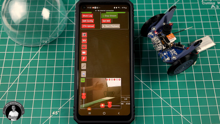
What you’ll want to do first is open a browser, and type its AP IP: 192.168.4.1 (this should be the same for you). You’ll see a panel like in the image above. Hit Start Stream to get the live video feed. To finish setup, go to Edit Config, scroll to Peripherals, enable Remote Control, set the buzzer beep duration to 1 second for motion detection, GPIO pin 6, and enable it. Set Voltage Check Interval to 1 min, low voltage warning at 3.5, monitoring GPIO pin to 5, and enable that too.
In RC Config, set the lamp GPIO pin to 43, set your speed thresholds, and motor pins to 1, 4, 2, 3 (in that order). Scroll up, save and reboot - this restarts the ESP32, so reconnect to its access point.
After a refresh, you’re ready. Tap the game controller icon to make the controller sliders appear for forward/reverse and left/right controls with proportionate speed as well as the lamp button. Hit one of the buttons accompanying the video stream window to go full-screen. Tap the bulb icon for simple on/off lights. For brightness control, move the lamp pin from RC Config to Peripherals -> Pin used for lamp, save, and adjust using the last slider in Camera Control.
When motion is detected, the bot starts recording and stops when movement ends; you can also start/stop manually. In Motion Detect and Recording, toggle detection on/off. In Playback and File Transfers, view or download clips, or pull the card and use your PC. The bot also beeps on low battery (starting at 3.5V) until turned off or restarted. Make sure it’s powered on to charge; at full charge, it should read 4-4.2V in the panel.
In Camera Control, you can adjust resolution: CIF for 30 FPS low-res, UXGA for ~5 FPS high-res, or SVGA for a good balance - I find SVGA works best. If you want to skip manual setup, grab my data folder with config + code in the ESP-ROLL project files: https://drive.google.com/drive/folders/1kDjNxRPIFhioJZheGN4Ns0RvkldiFyfA?usp=sharing
For deeper setup help, watch this video: https://youtu.be/k_PJLkfqDuI
With the ESP-ROLL almost ready, let’s do a brief drive test to see how it behaves!
14. Driving and Tuning The Robotic Sphere
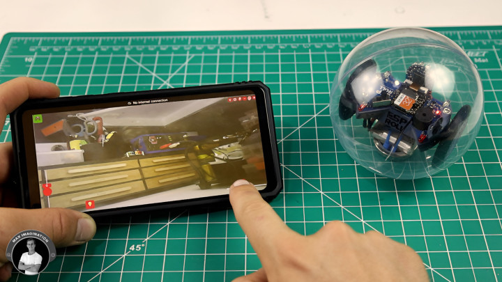
Controlling it is fairly straightforward: Move the right slider to steer it - it’ll simply turn in its place. Move the left slider to make it roll forward or reverse. And if you combine the two controls, you can make it roll while turning.
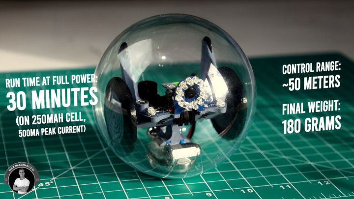
However, if you experience it wobbling or worse - flipping around like I had it, you need to give it some heavier weights. Around your home, think of any heavy metal parts of the right size - the heavier, the better. I went with a steel cover originally used to house a neodymium magnet, attached it under the battery, slapped on a couple of magnets, and added some long cap nuts. My weight weighs 50 grams alone and 65g with the 8g battery and other 7g weight we added earlier while the ball bot itself (no sphere shells, weights, or battery) weighs just about the same (67g). The final weight of my ball bot comes to 180g with the sphere shells.
Seeing how the ball bot behaves after adding heavier weights makes a huge difference. Again the more weight you add without scraping the inside of the ball, the better it will perform - resulting in smoother FPV footage too.
15. Drive-testing the ESP-ROLL
With the ESP-ROLL fully set up, it’s time to see how it performs in the real world.
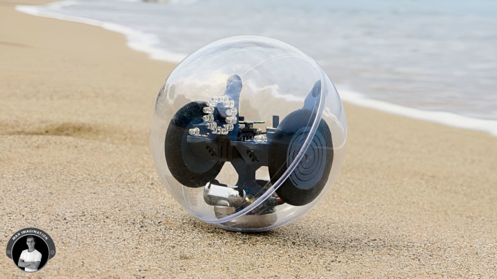
On smooth indoor tiles and hardwood floors, it glides with ease. It handles carpet surprisingly well too - and I find carpet to be the best surface for driving the robot, since it has decent grip and causes the least scratching on the plastic ball compared to other surfaces. Outdoors, it can roll over grass and even sand at the beach - though sand can slow it down depending on how fine or deep it is. I did take it on sea water to see if it could roll across wet surfaces or float, it did well moving slowly forward, but some tiny scattered drops of water found their way inside the shell - with clear tape sealing it. I wouldn’t recommend using the ESP-ROLL near water unless you properly seal the shell with silicone or electrical tape to keep the electronics safe.
For fun, I also ran it through a simple obstacle course with cups and a cardboard ramp, which really showed off how responsive/maneuverable it is on flat and mixed terrain (It can turn sharply on the spot or take wide arcs—whichever you prefer). And utilizing the onboard camera, you can even experience driving it in first-person, adding a whole new level of control and immersion. To see all of this, I highly recommend watching the full video on the ESP-ROLL linked at the bottom of this blog.
The ESP-ROLL’s run time on a 250mAh cell (500mA being drawn) is around 30 minutes and can be easily increased to an hour with a 500mAh cell that fits. Its control range comes in at around 50 meters and could extend to 100 meters with a better antenna.
16. Ready to build your ESP-ROLL?
If I’ve inspired you to build the spherical robot, go check out the links at the top of this blog or video’s description. I’ve dropped all of what you need to get started - parts list, diagrams, code, 3D files, PCB gerbers - everything to get your ball rolling!
So, start by acquiring the parts, take it a step at a time - and before you know it, you’ll have your own little rolling robot cruising around your home.
So, start by acquiring the parts, take it a step at a time - and before you know it, you’ll have your own little rolling robot cruising around your home.
Watch the full tutorial video here for better visuals on building the ESP-ROLL - and seeing how it rolls:
Commenti (1 commenti)