


Progressive blinking LED
An LED slowly fading in and out is more attractive than a blinking one. Here is a circuit to do that using an NE555.
The amplifier in class A I have made has a standby mode activated by the remote control of the preamp I also realized. A blue LED continuously lit indicates that the amp is working. To signal that the amp is in standby, I didn’t want a flashing ON/OFF led, but a led that turns on and off gradually. So I made a circuit based on NE555 to get this result.
In the Eagle schematics attached, the values given to R3, R4 and C3 produce a frequency of 0.3 Hz and a duty cycle of 51% with the 555 in astable mode. The transistor T4 inverts the output (3) of the 555 and the transistors T3 and T2 increase the output power.
The RC filter made up of R8 and C1 makes it possible to obtain the triangular signal necessary for the progressive switching on and off of the led. The latter is controlled by T1.
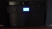
In the picture, the amp is at the bottom with the led on, the preamp is on top with its LCD graphic screen which displays the parameters (active source, volume level etc.) and 2 VU meters, all controlled by a micro-controller.
In the attached files, you can find the schematics, the printed circuit layout and a small video showing the progressive blinking of the led.
In the Eagle schematics attached, the values given to R3, R4 and C3 produce a frequency of 0.3 Hz and a duty cycle of 51% with the 555 in astable mode. The transistor T4 inverts the output (3) of the 555 and the transistors T3 and T2 increase the output power.
The RC filter made up of R8 and C1 makes it possible to obtain the triangular signal necessary for the progressive switching on and off of the led. The latter is controlled by T1.
In the picture, the amp is at the bottom with the led on, the preamp is on top with its LCD graphic screen which displays the parameters (active source, volume level etc.) and 2 VU meters, all controlled by a micro-controller.
In the attached files, you can find the schematics, the printed circuit layout and a small video showing the progressive blinking of the led.
Want to build a project?
Bring your design to life with the Elektor PCB Service, powered by Eurocircuits. Upload the project files and order professionally manufactured PCBs or assembled boards through a proven European production platform.
Supporting KiCad, Eagle, Gerber, and ODB++ formats, the service is suitable for everything from prototypes and validation builds to series production and volume manufacturing.
Made in Europe. Fast. Reliable. Professional.
Commenti (2 commenti)