Make a 200W Pure Sine Wave Inverter using the EGS002 SPWM Driver board.
Features:
1. Intelligent SPWM control
2. Silent, stable, and efficient
3. Ideal for sensitive electronics
4. Output Voltage: 220V(A.C.)
5. Output Frequency: 50Hz
6. Output Power: 200W
7. Input Voltage: 12V(DC)
INTRODUCTION In my previous project on the inverter, I showed you how you can build a modified square wave inverter using Arduino. The inverter worked well; however, the problem is that the output waveform is a modified square wave, rather than a pure sine wave. So, inductive loads like motors and transformers produce a humming sound, and it is not desirable. The main reason behind this humming sound is the presence of harmonic components in the output of the inverter. Also, we cannot connect some sensitive electronic appliances like a laptop, a computer, and a smartphone to it. Today, in this project, I will create another inverter that outputs a pure sine wave. For making this inverter, I am using SPWM(Sinusoidal Pulse Width Modulation). For implementing/generating SPWM, I am not using any microcontroller or microcontroller-based development board because I want to keep this project as simple as possible for you. For generating SPWM for my inverter, I am using EGS00,2, which is the most popular SPWM inverter module, and this module does not require any program(Code) that must be uploaded to it before using it. You can easily get this module.
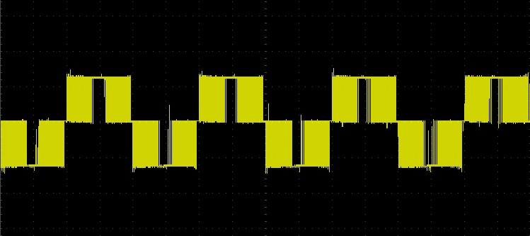
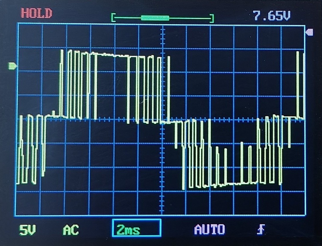
SPWM(Sinusoidal Pulse With Modulation) Sinusoidal Pulse Width Modulation, aka SPWM, is a technique primarily used in power electronics to generate a signal that approximates a pure sine wave. SPWM generates a series of pulses with varying duty cycles according to the sinusoidal reference signal. With SPWM, we can also control the power delivered to a load. The waveform of SPWM is shown in Fig.1. Fig.2 shows the output waveform of my inverter on DSO138. Fig.1 Unipolar SPWM Waveform 1
Fig.2 Unipolar SPWM Waveform 2 Unipolar SPWM Unipolar SPWM is a type of SPWM. In unipolar SPWM, the output voltage switches between 0 and +Vdc(or 0 and -Vdc) in the half cycle. generated by comparing the sine wave with a single carrier. Lower harmonic distortion, simpler filtering, and reduced switching loss. Common in single-phase inverters and applications requiring smoother output. The waveform shown in Fig.1 is unipolar SPWM.
Configure the EGS002 Module in Unipolar SPWM Mode The EGS002 module supports both unipolar and bipolar SPWM types. When you purchase a new EGS002 module, the mode is already set to unipolar SPWM as a default by the manufacturer. To configure the EGS002 module for unipolar SPWM mode, connect the MODSEL pin(pin-20 on the EG8010 chip) to GND(ground).
Components List
Resistors
R1–R4: 10kΩ
R5–R8: 10Ω
R9: 2.2kΩ
R10, R11: 100kΩ
R12: 1kΩ
RT1: 10kΩ NTC thermistor
VR1: 10kΩ potentiometer
Capacitors
C1: 1000µF/16V
C2: 10µF/63V
C3: 0.1uF
C4: 0.01uF
C5: 2.2µF/400V
C6: 4.7µF/63V
Semiconductors
Diodes: D1–D4, D9: 1N4148; D5–D8: FR107
BJT: S8050
MOSFETs: Q1–Q4: IRF3205
Voltage Regulator: LM7805
Other Components
LED: 5mm red
Switch: SW1
PCB Terminal: 2-pin
Heat Sink: HS1, HS2, HS3 and HS4 for MOSFETs
Cooling Fan: 12V
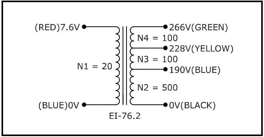
Transformer: UPS transformer (228V output using black and yellow wires; red and blue for H-bridge)
Step-Down Transformer: 230V to 9V (for testing)
Battery: 12V, 7Ah sealed lead-acid
Load: 220V/100W incandescent lamp with holder
EGS002 Module: SPWM inverter module
Headers: 1x17 female headers
PCB: 8x12cm (or perfboard)
Necessary Tools
60W Soldering Iron(with adjustable temperature)
Soldering Wire
Soldering Flux
Screw Driver
Digital Multimeter
DSO138 Oscilloscope Kit
A Brief Description of Used Parts
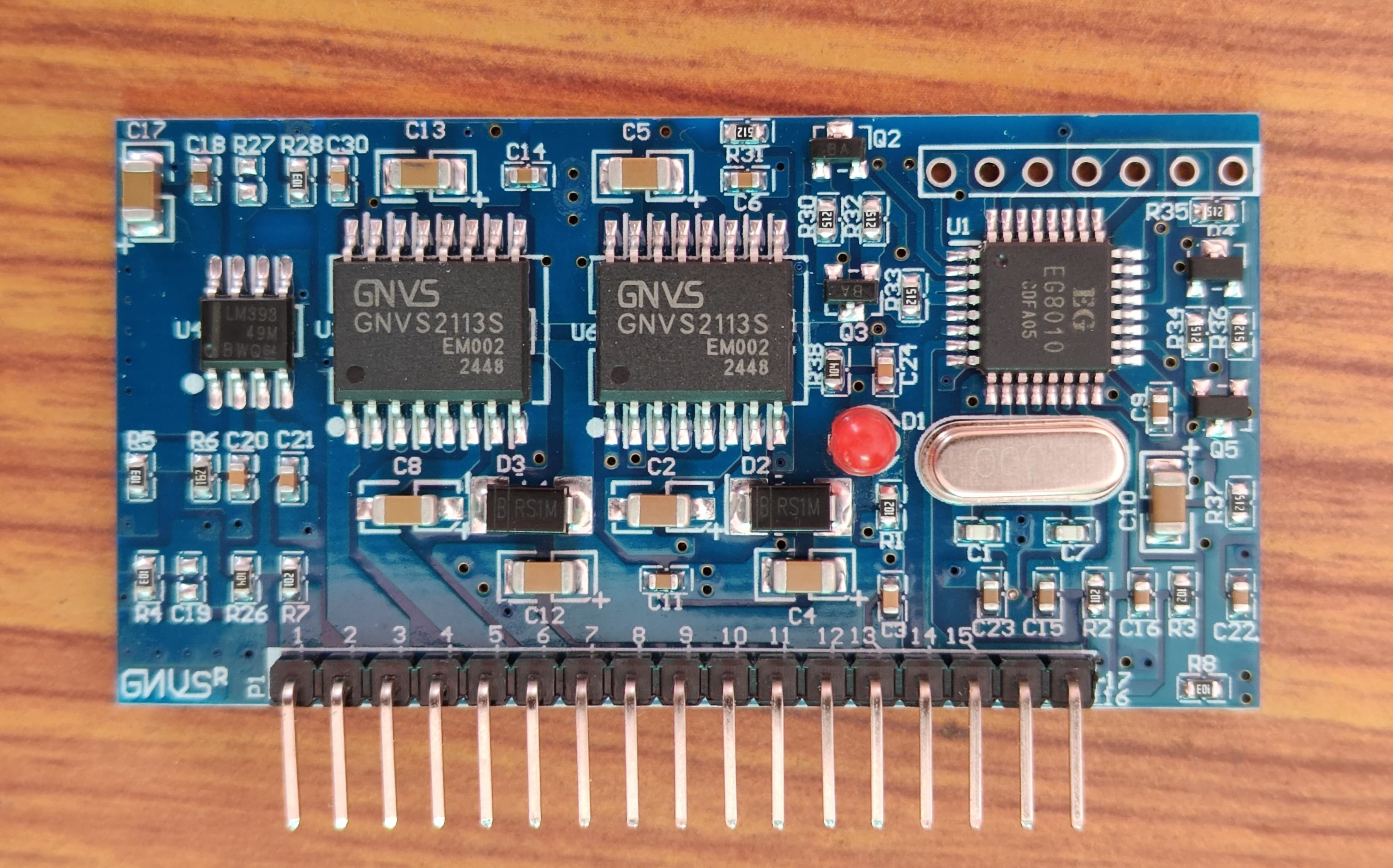
EGS002 Module EG8010 is a driver board specifically designed for a single-phase pure sine wave inverter. It is based on the EG8010 IC and the IR2110S/IR2113S high and low-side MOSFET driver IC. This board consists of two IR2110S chips instead of a single one because both ICs drive two separate MOSFET half bridges. The LM393 voltage comparator IC is also used on this board for overcurrent protection. The top and bottom views are shown in Fig.3 and Fig.4, respectively. Fig.3 EGS002 Module (Top View)
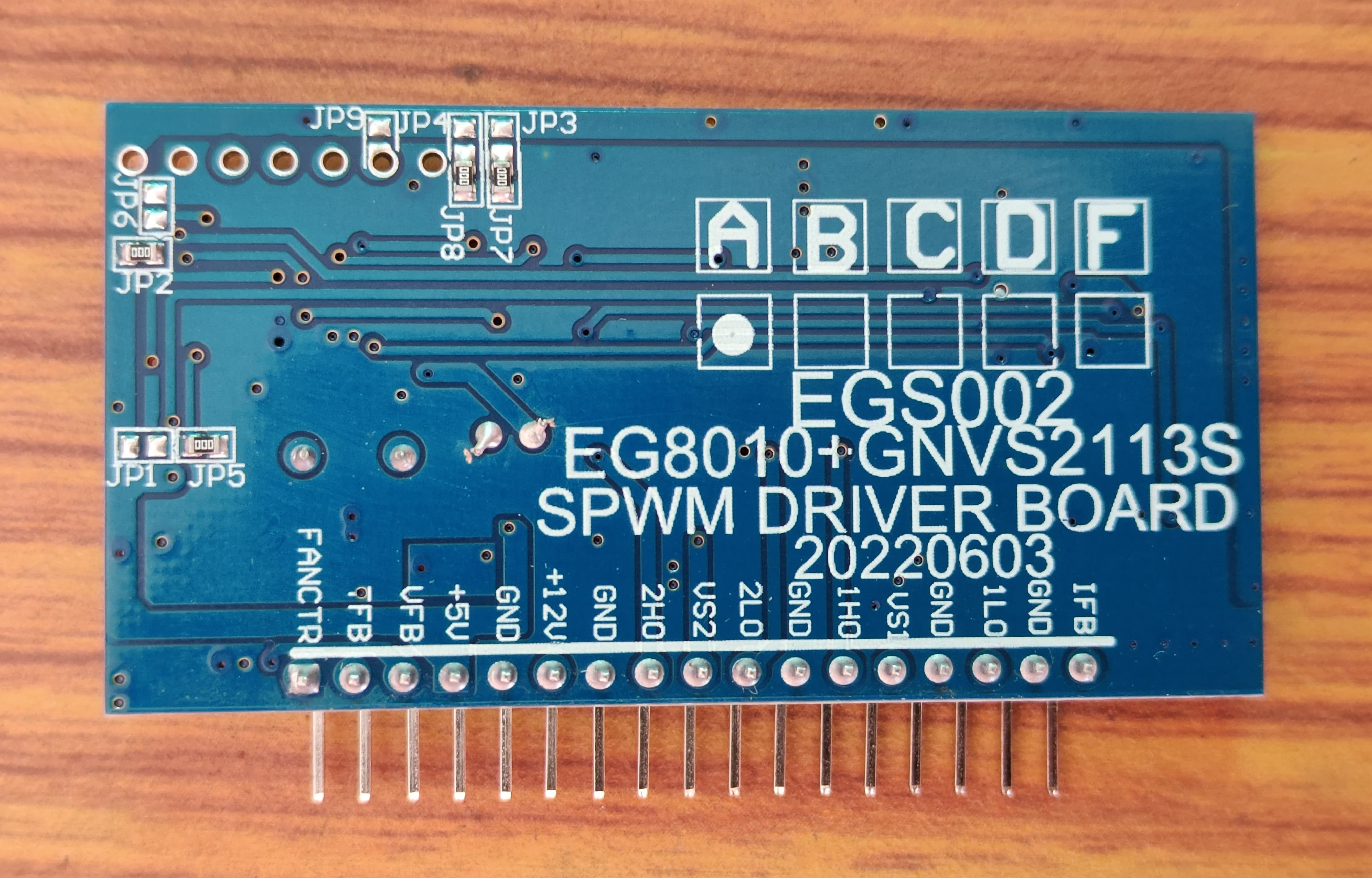
Fig.4 EGS002 Module (Bottom View)
EG8010 EG8010 is an application-specific integrated circuit(ASIC) that has been designed for making a pure sine wave inverter. It is based on CMOS technology, and this IC integrates a SPWM generator circuit, a dead time control circuit, a soft start circuit, a protection circuit, RS232 serial communication, and a 12832 serial LCD interface. With EG8010, we can easily generate a 50/60Hz pure sine wave with high accuracy. The generated pure sine wave has low harmonic distortion due to the usage of an external 12MHz crystal oscillator.
Features of EGS002 Module
5V DC supply for EGS8010 IC.
12V DC supply for MOSFET driver ICs(IR2110S)
Unipolar and bipolar modulation support.
External 12 MHz crystal oscillator.
23.4 kHz PWM carrier frequency.
dead time control(300ns, 500ns, 1.0us and 1.5us).
Soft start mode.
50 or 60 Hz fixed frequency output.
0 - 100Hz pure sine wave with frequency adjust.
0 - 400Hz pure sine wave with frequency adjust.
Output voltage feedback.
Output current feedback.
Real-time temperature feedback.
External serial LCD support for displaying output voltage, current, frequency, and temperature.
Support serial communication to set the output voltage, frequency, and other parameters.
Overvoltage, Undervoltage, Overcurrent and Overheating protection.
Includes two MOSFET drivers(IR2110S or IR2113S) for driving two MOSFET half bridges.
3mm RED LED for indicating over-voltage, under-voltage, over-current, and over-temperature.
Parameters can be adjusted by shorting or opening jumpers(from JP1 to JP9).
Includes Cross-Condition Prevention Logic
EGS002 Jumper Settings: EGS002 has nine jumpers(JP1 - JP9) for changing the output parameters of the board: Selecting output frequency
If JP1 is short, it selects the A.C. output frequency of 60Hz.
If JP5 is short, it selects the A.C. output frequency of 50Hz.
Enable/Disable soft start mode
If JP2 is short, it enables a 3-second soft start mode.
If JP6 is short, it disables soft start mode.
Selecting dead time
If both JP7 and JP8 are short, the dead time is 300ns.
If both JP3 and JP8 are short, the dead time is 500ns.
If both JP4 and JP7 are short, the dead time is 1.0us.
If both JP3 and JP4 are short, the dead time is 1.5us.
Turn on/off LCD backlight If JP9 is short, the LCD backlight is on, but if JP9 is open, the LCD backlight is off.
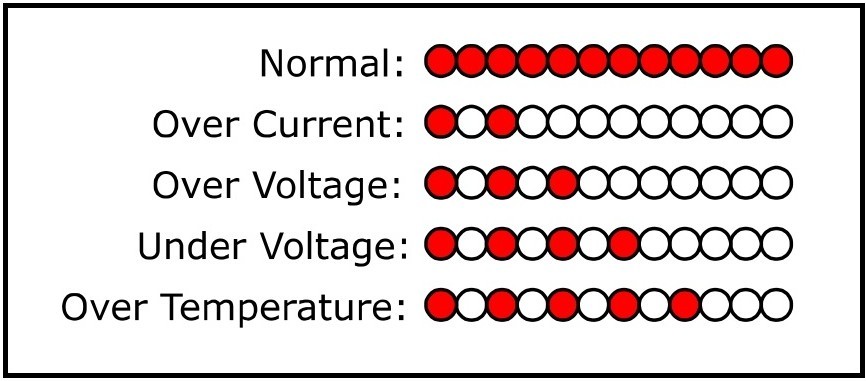
EGS002 LED Warnings: The EGS002 module has a 3mm red LED for warning indication.
Normal: Always on.
Overcurrent: Blink twice, off for 2 seconds, and keep cycling.
Overvoltage: Blink thrice, off for 2 seconds, and keep cycling.
Undervoltage: Blink four times, off for 2 seconds, and keep cycling.
Overtemperature: Blink five times, off for 2 seconds, and keep cycling.
Fig.5 LED Warning Indication
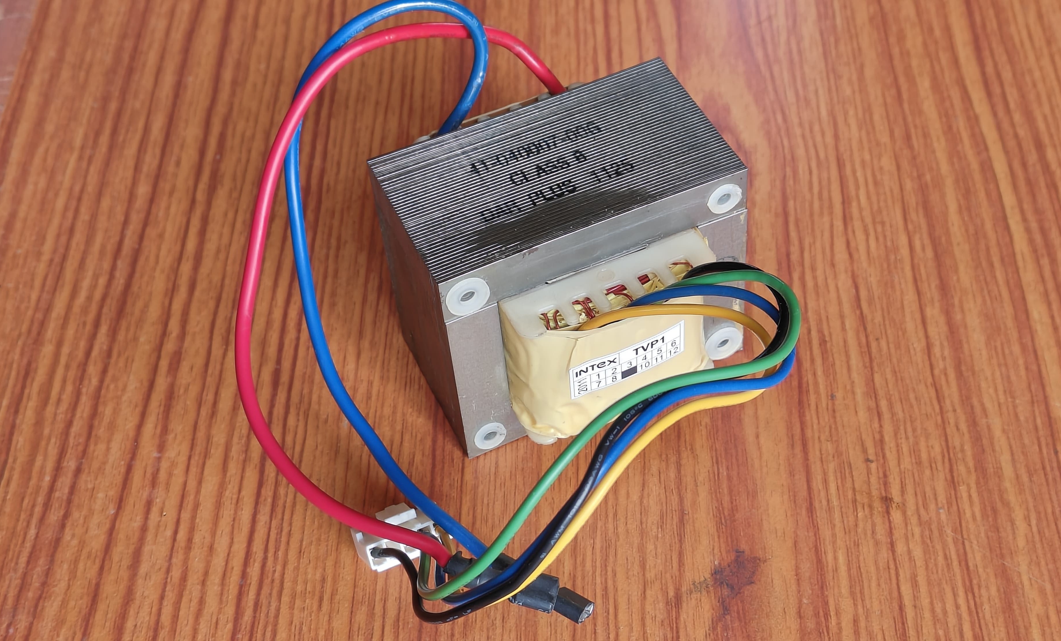
UPS Transformer For my inverter, I am not designing a new transformer; instead, I am going to use a computer UPS transformer shown in Fig.6. I have taken this transformer from an old computer UPS. Although this transformer has four wires(black, blue, yellow, and green) at the high voltage side and two more wires(red and blue) at the low voltage side. The black wire is neutral(0V), and blue, yellow, and green wires have output voltages of 190V, 228V, and 266V, respectively. I am using the black(0V) and Yellow(228V) wires as mains voltage output for my inverter. Leave the green and blue wires as it is. You have to connect red and blue wires(at the low-voltage side)to the output of your H-bridge. Fig.6 UPS Transformer Fig.7 Transformer Winding/Voltage Data
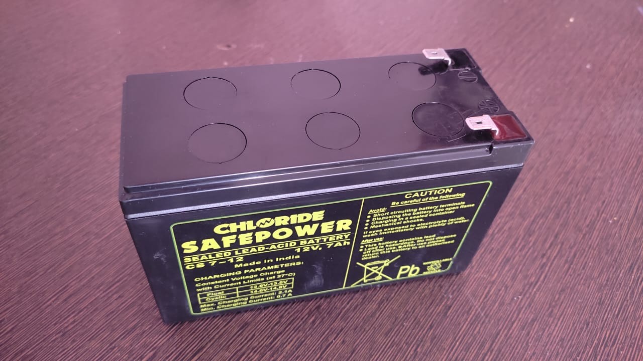
Battery For supplying DC power to the inverter, I am using a 12V, 7Ah sealed lead-acid battery. This battery is widely used in computer UPS, so I got it easily. Before using the battery, please check its voltage with a digital multimeter to make sure it is charged or not. If the battery voltage value is greater than or equal to 13.0V, it is fully charged, and if the voltage value is in the range 11.0V - 12.5V, it is moderately charged. But if the voltage value is below 11.0V, it indicates that the battery is discharged. If your battery is discharged, then charge it with a proper lead-acid battery charger. The charging voltage of this lead-acid battery is 13.8V, which is also marked on the battery as shown in Fig.8. Fig.8 12V/7Ah Sealed Lead-Acid Battery
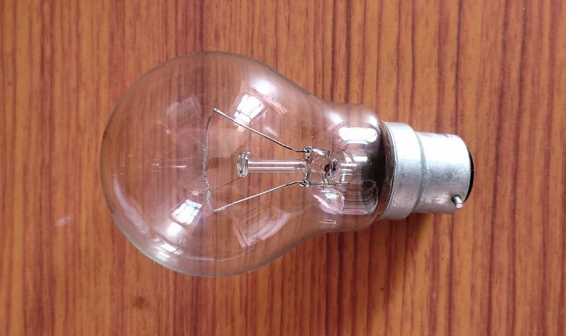
INCANDESCENT LAMP For testing, I am using a 220V/100W incandescent lamp. Fig. 9 220V/100W Incandescent Lamp
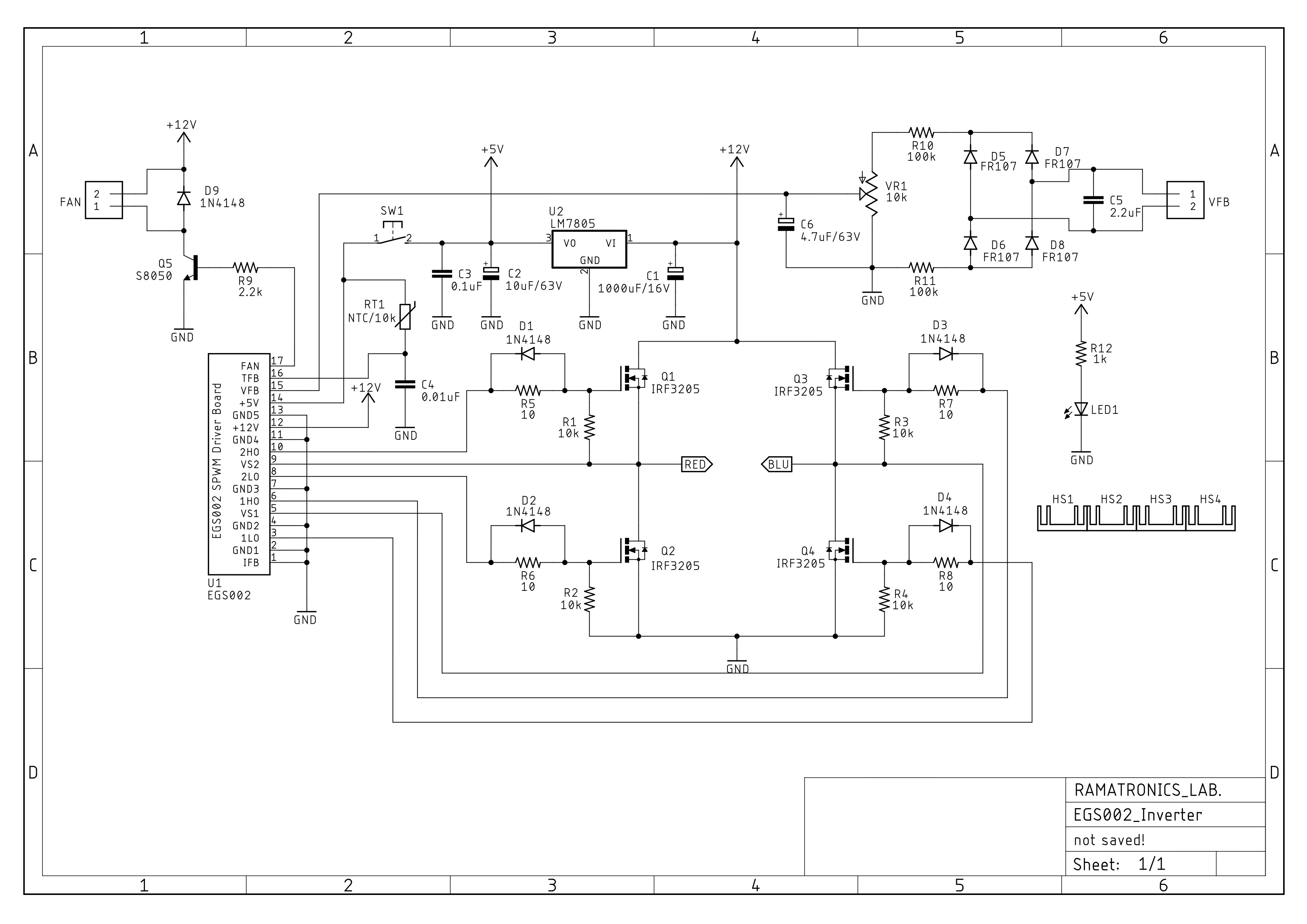
SCHEMATIC DIAGRAM Fig.10 Schematic Diagram
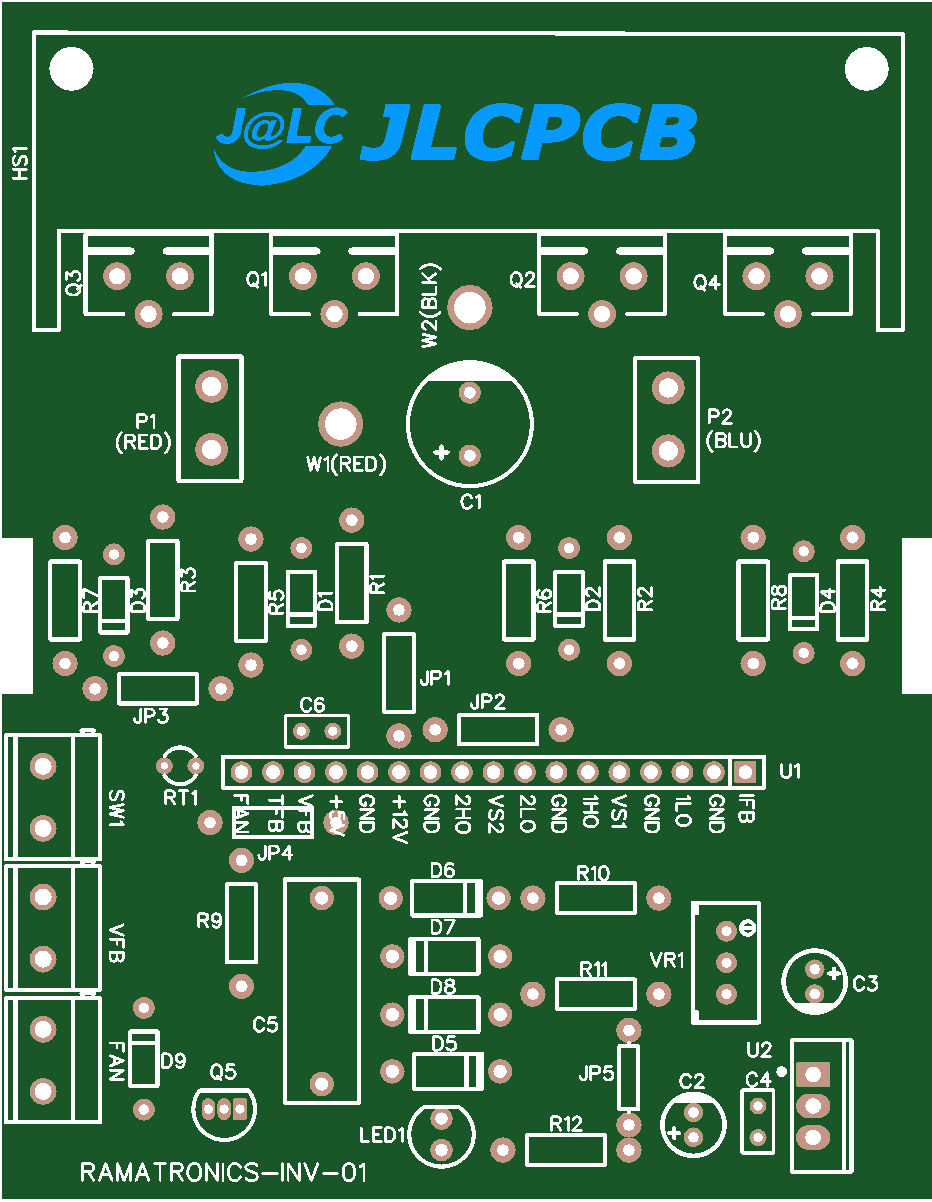
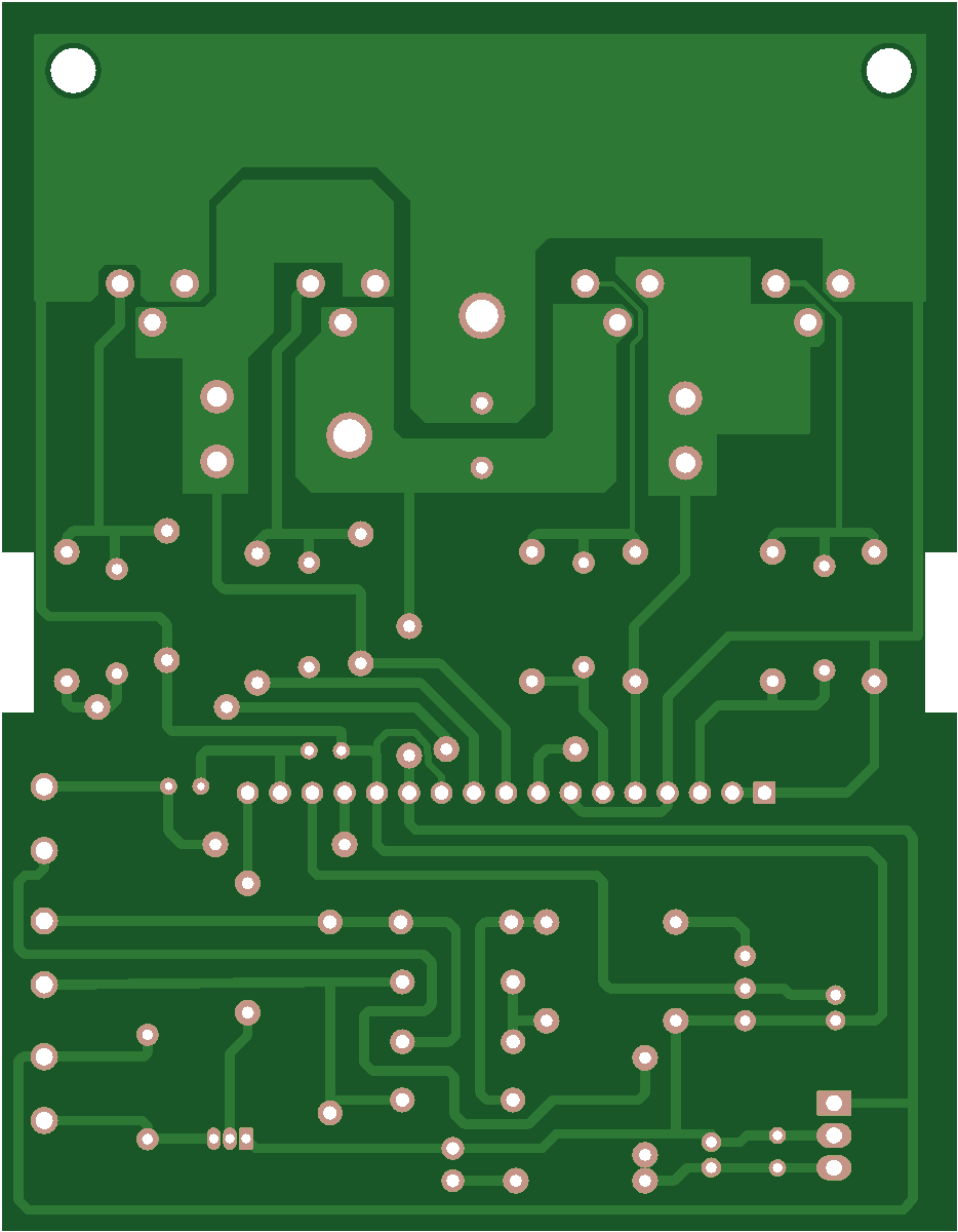
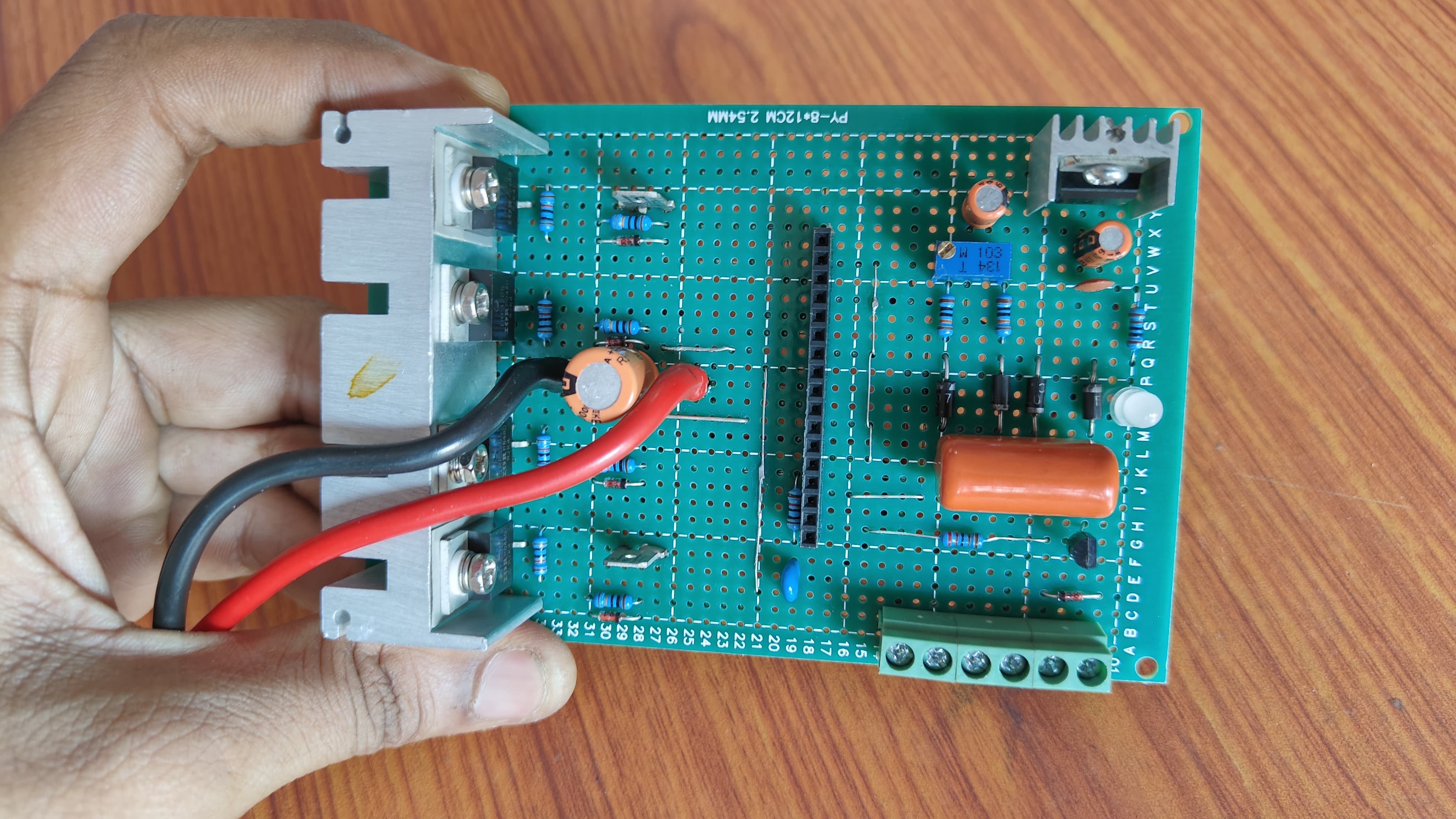
Make a Professional PCB(First Option) I have designed a nice PCB for my inverter using EasyEDA, a schematic and PCB design software. The PCB images are shown in Figs. 11 and 12. Here, I have shared the Gerber file of my PCB, so you can download it to fabricate a more professional-looking PCB for your inverter. Fig.11 PCB Top View 1 Fig.12 PCB Bottom View 1
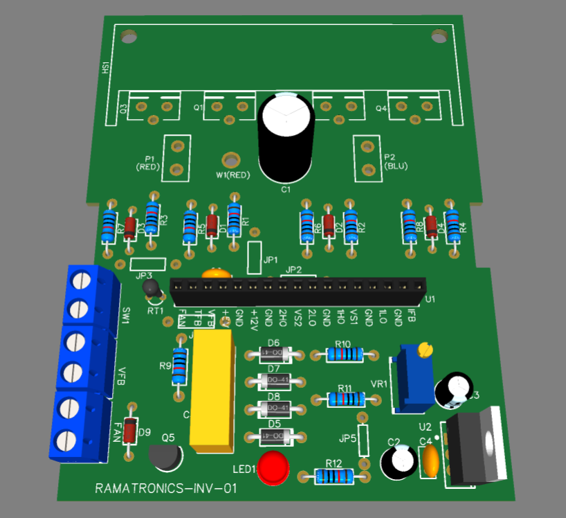
3D View of PCB Fig.13 PCB 3D View
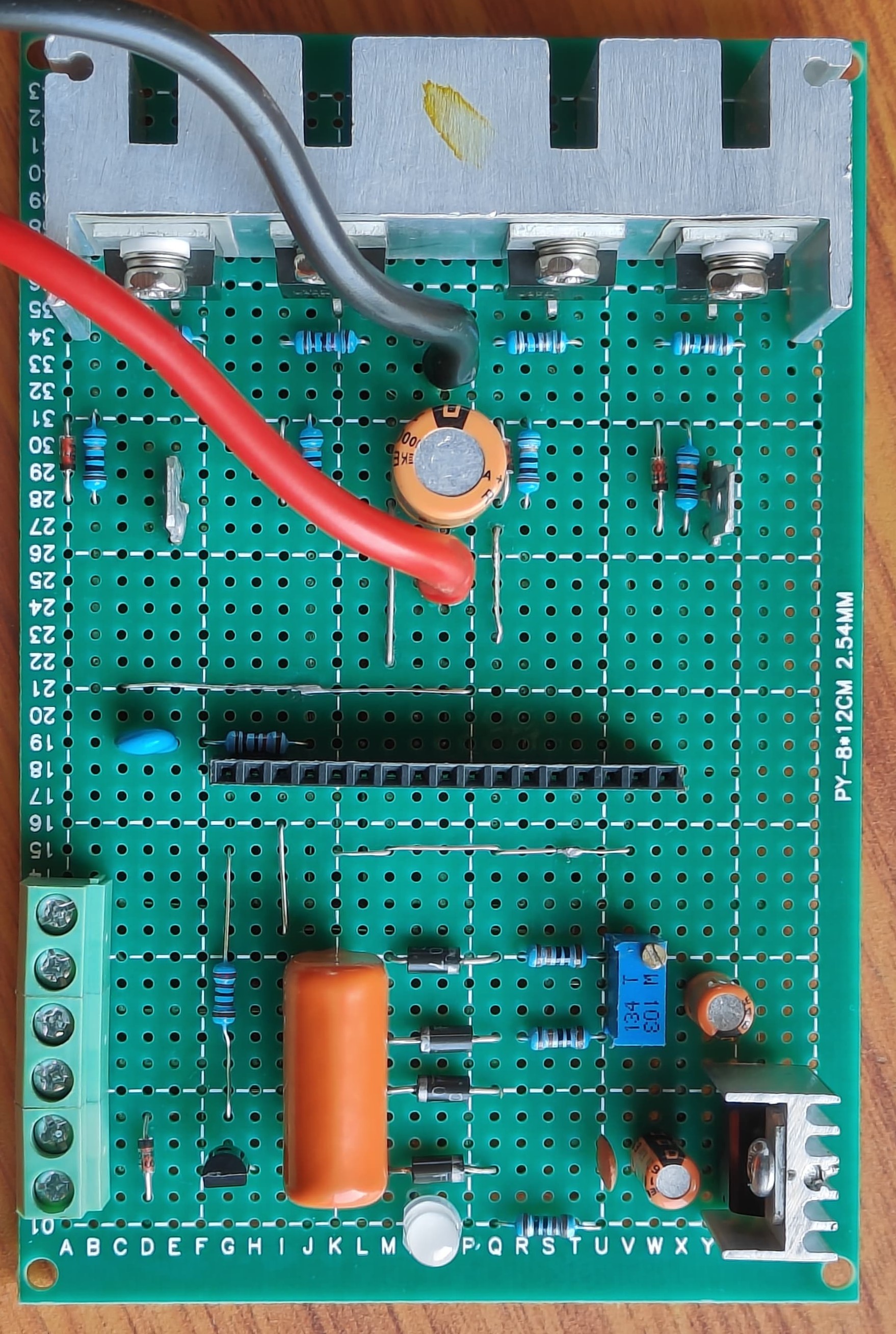
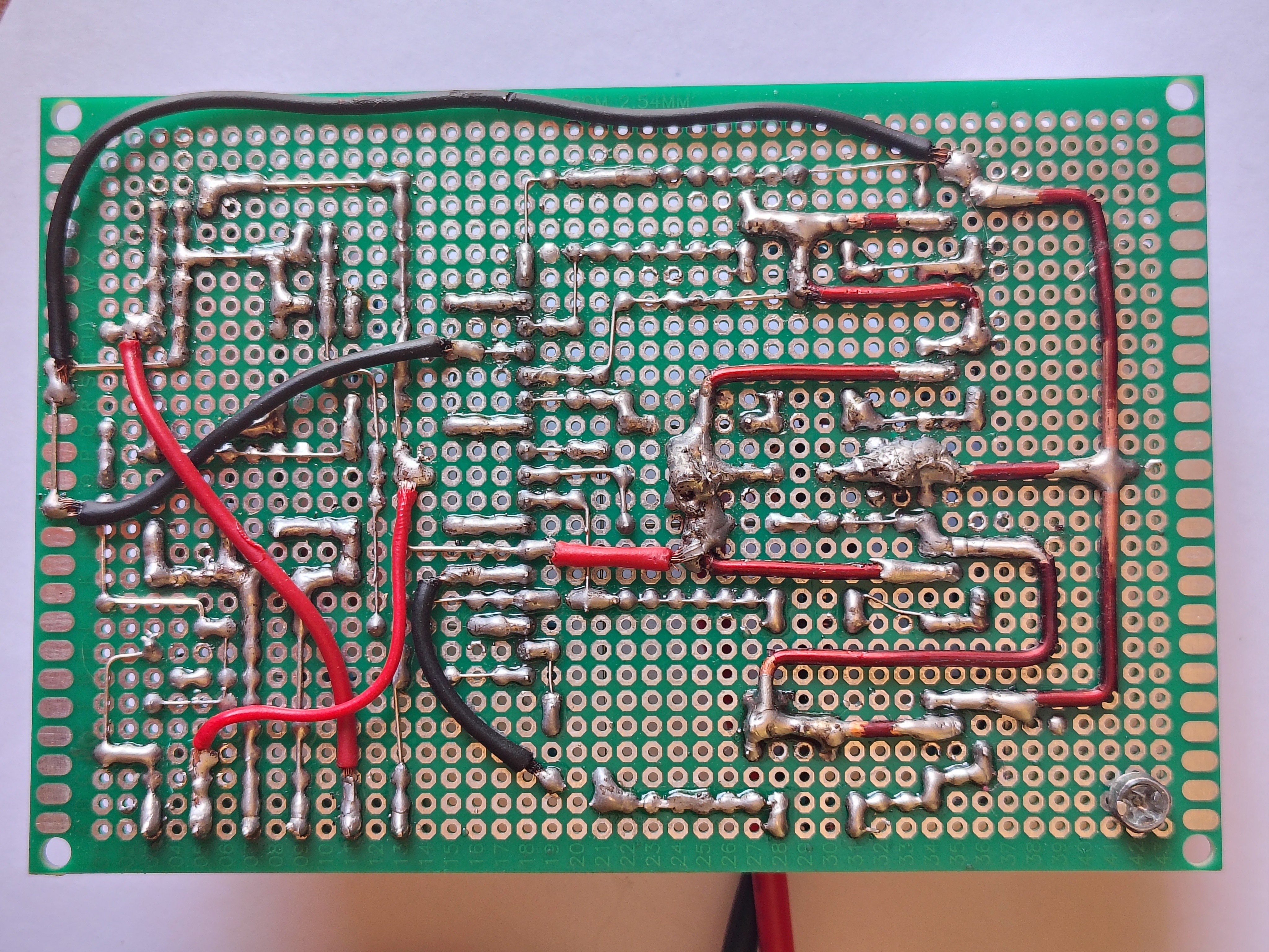
Making the Inverter Circuit On a Perfboard(Second Option) Although I have provided the Gerber file of my PCB here for making a more professional-looking printed circuit board(PCB) for this inverter project but if anybody is not comfortable with the production of PCB, then I have a second option for them. I have created another circuit of this inverter on a perfboard as shown in Figs. 14 and 15. So the users who can't fabricate PCBs can go this way. Fig.14 PCB Top View 2
Fig.15 PCB Bottom View 2 Fig.16 PCB Top View 3
Adjust the Output voltage You can adjust the output voltage of the inverter with a 10k potentiometer(VR1) on the inverter PCB. If you rotate the knob of the potentiometer in clockwise direction, the output voltage of inverter slowly rises and if you rotate the knob in counterclockwise direction, the output voltage of inverter slowly decreases. You can easily rotate the knob of potentiometer with an screw driver having a flat tip. In my country(i.e., India), the mains voltage is 220V, so I set the output voltage of my inverter around 220V.
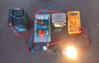
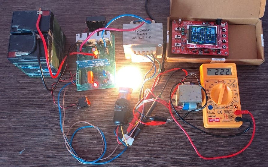
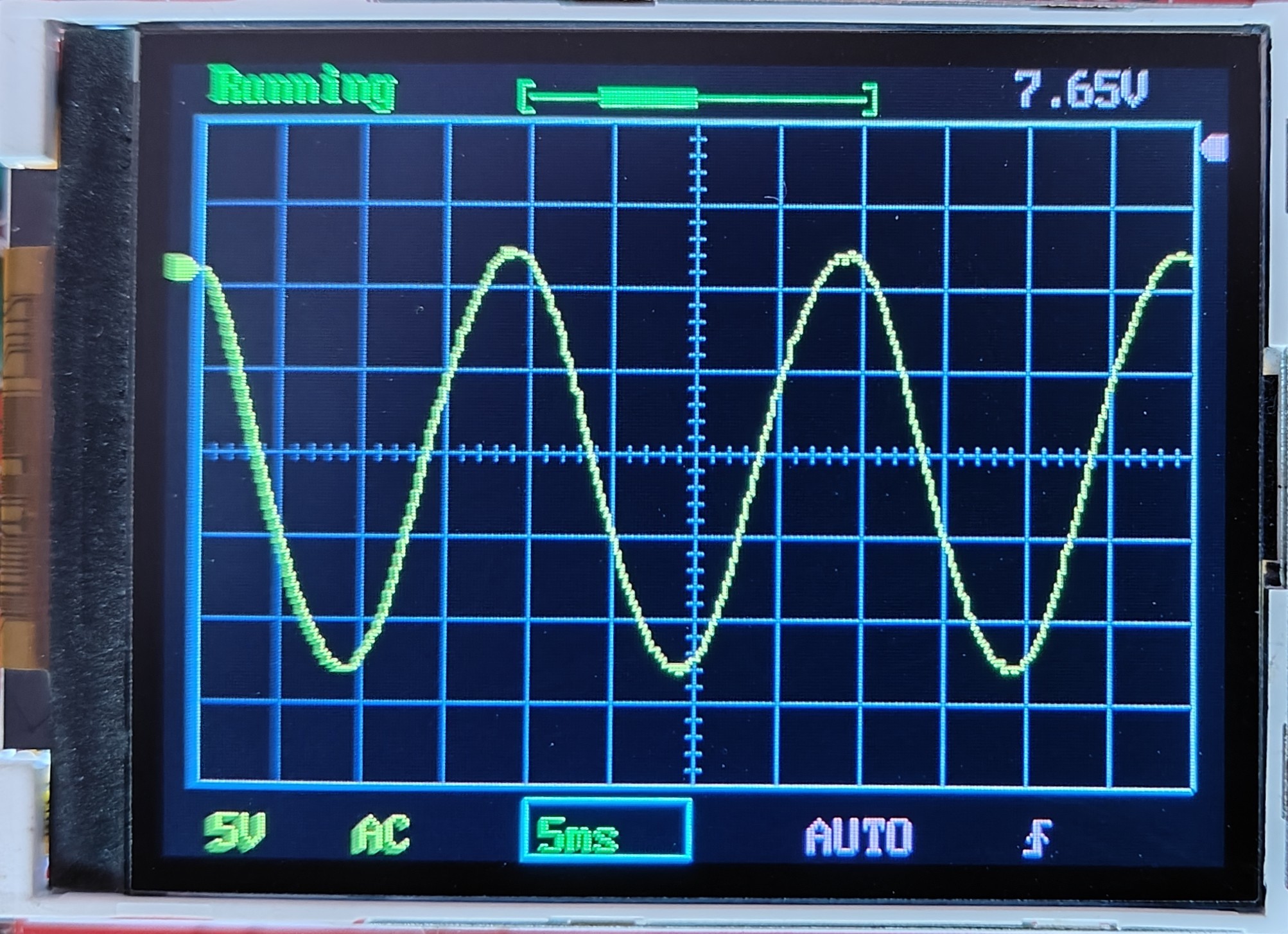
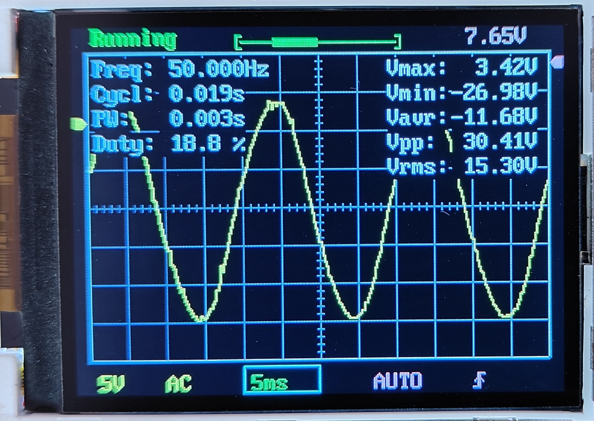
TestingtheInverter'sOutput Waveform Fig.17 Testing output waveform Testing the waveform of the output voltage, I am using a DSO138 oscilloscope kit. The output voltage of the inverter is 220V A.C., so it is not safe to measure such a high voltage directly with the oscilloscope. For safe measurement of this voltage, I am using a 230V to 9V step-down transformer. Fig.17 shows the output waveform of my inverter at a 100W load. The frequency of the output sine wave is 50.0 Hz, as shown in Fig.18. Fig.18 Output Waveform 1
Fig.19 Output Waveform 2 Results
The inverter delivers a stable 220V, 50Hz pure sine wave with minimal harmonic distortion, suitable for sensitive electronics and inductive loads. The EGS002’s protections ensure safe operation, with the LED indicating any faults. The 100W load test confirmed reliable performance, and the adjustable output voltage allows flexibility for different regions.
Tips and Precautions
Safety: Handle 220V AC with care; use insulated tools and ensure proper grounding
Battery: For loads >100W or extended use, consider a higher-capacity battery.
Cooling: Verify the fan and heat sink adequacy for prolonged operation.
Troubleshooting:
Check LED blink patterns for fault diagnosis.
Verify transformer and MOSFET connections if no output is observed.
Enhancements: Add an LCD for real-time monitoring of voltage, current, and temperature.

Commenti (2 commenti)