Elektor vanta una lunga tradizione nella pubblicazione di progetti di orologi. Diamo un'occhiata a un classico: il MOS Clock 5314, che ha rappresentato uno dei primi esempi di utilizzo della tecnologia MOS per orologi elettronici affidabili e facili da assemblare.
Elektor has a long history of publishing clock projects. Let’s take a look at a classic — the well-received MOS Clock 5314.
The Circuit
Published in 1974, the MOS Clock 5314 was a digital clock project based on the MM5314 IC, which handles timekeeping and drives a six-digit, seven-segment LED display. It simplified digital clock construction by requiring minimal external components. The design showcased early use of MOS technology to build reliable, easy-to-assemble electronic clocks.
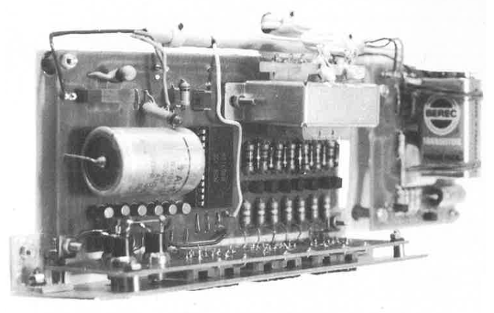
The MOS Clock 5314
The clock, featuring the MM5314, was designed to indicate the time in hours, minutes, and seconds. Users could choose between a 24-hour and 12-hour cycle. Refer to the circuit diagram. Apart from the MM5314 only few components were needed to build a complete clock.
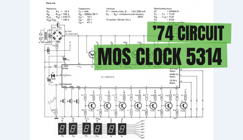
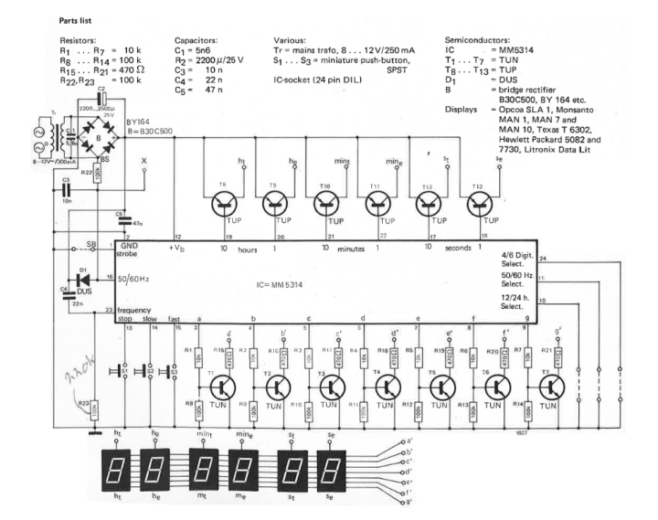
The complete circuit.
"Perhaps somewhat unusually, the circuit description starts with the supply, because it is from there that the counter pulses are derived," the original article states. "Since the supply voltage for the IC need not be stabilized, the source has been kept as simple as possible. The d.c. supply voltage may be anything between 8 V and 17 V. The half cycles of the 50 Hz mains are fed to the pulse input via a decoupling network R22/C3. This input is protected against overloading by means of diode D1."
The PCB
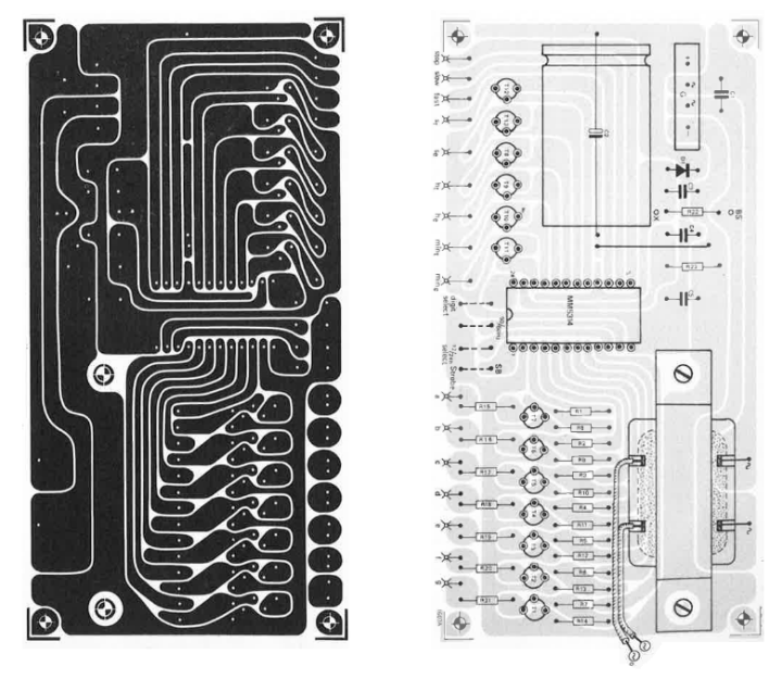
The boards were meant to be small so that the entire unit could be housed in a compact, attractive enclosure. Space was reserved on the board for the supply transformer and electrolytic capacitor C2 so that, if necessary, a fairly large types could be used. The article explained that all terminals and controls (50/60 Hz selection, strobe, etc.) were placed in a row on one side of the board, directly opposite the terminals they were connected to on the display board. The display board held the displays and small push buttons for “stop,” “slow,” and “fast.”
The MOS Clock 5314 PCB.
The Original Project
The article, “MOS Clock 5314,” appeared in Elektor December 1974. You can freely access the article during the two-week period following the publication of this news item. If you start a project of your own, consider sharing your progress on the Elektor Labs platform!
Editor's Note: This article originally appeared in a 1974 edition of ElektorMag. Keep in mind that, given the project’s age, some components or products may no longer be available. However, we believe the content will inspire you to start new electronics projects of your own.
Registrazione
Notifica tag: Iscriviti al tag Circuits & Circuit Design e riceverai un’e-mail non appena un nuovo contenuto a riguardo verrà pubblicato sul nostro sito web!


Commenti (0 commenti)