
Dip Meter Ultra-Minimalista
su
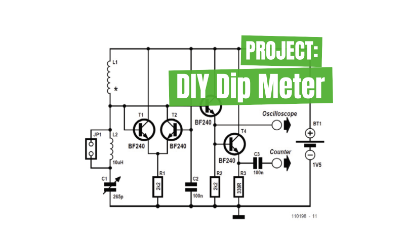
Dip Meter Circuit
In days gone by, a radio amateur always had a (grid) dip meter close to hand in the ‘shack’. Now that people can afford oscilloscopes, the poor old dip meter has lost its importance and is frequently no longer to be seen except perhaps in . Actually, this is a shame because many seemingly complex tasks are easy to carry out with a dip meter. Anyone who’s interested (perhaps the second time around) can easily build one rapidly with this very simple but adequate circuit.
The interesting question is what do you actually need from a dip meter?
- A visual display of the dip? Nope, the ‘scope can handle that task.
- A large frequency scale? Not necessary, as you can connect a frequency meter for this.
- An array of coils? We don’t need these because we can use a jumper to change range (no coils to lose anymore!).
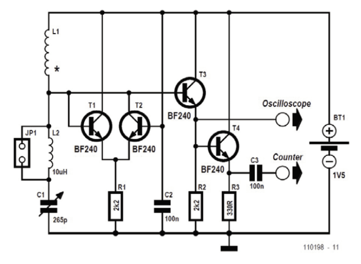
The sensor coil L1 has ten turns and is wound using an AA-size battery as a former. This coil will allow us to over the range from 6 MHz to 30 MHz. With jumper JP1 open an additional fixed inductance of 10 μH comes into circuit. The frequency measurement range is then from roughly 2.5 MHz to 10 MHz. The switch may be replaced by a jumper.
Take Measurements
To take measurements, you hold a resonant circuit close to the sensor coil. Tune the rotary capacitor C1 slowly to and fro in order to find the resonant frequency, at which the oscillator amplitude decreases somewhat. The frequency can then be read directly off the oscilloscope. To obtain a very accurate measurement, you can additionally connect your frequency meter (counter) to the second output.
Editor's Note: This article (200199-01) first appeared in Elektor July/August 2020.


Commenti (0 commenti)