
Inductive AM Transmitter
The Elektor AM Transmitter Kit allows streaming audio to vintage AM radio receivers. Based on a Raspberry Pi Pico microcontroller module, the AM Transmitter can transmit on 32 frequencies in the AM band, from 500 kHz up to 1.6 MHz in 32 steps of approx. 35 kHz.
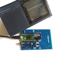
In 2015, Elektor published a simple circuit for an inductive AM transmitter that let you stream music to a vintage tube-based AM radio receiver. (Of course, it also worked with transistor radios as long as they have an AM radio band.) The circuit used an Arduino UNO, an add-on shield with a display and a pushbutton, and a little circuit assembled on a piece of prototyping board. Even though this system worked fine, it didn’t have the looks required for something to be placed in sight, in a living room or study or so. Also, it was not very robust. In this project we revisit the ten-year-old project and turn it into something more practical. While doing so, we learn how to integrate a PIO program in an Arduino sketch.
Even though the Atmega328 still is a great microcontroller and the Arduino UNO a practical platform for using it, today, then years later, there are other solutions to achieve the same results in a somewhat more elegant way. Therefore, we replaced the Arduino UNO by a Raspberry Pi Pico as it is much smaller and faster, and also cheaper. Furthermore, we replaced the LCD by one of those a small OLED displays that are so popular these days.
Next comes the modulator. It isn’t very visible, though. To see it, imagine node R9/R10 connected to the drain of a N-type MOSFET that has its source connected to ground and its gate connected to GPIO2. The gate is driven by the carrier signal. When the gate is driven high, the MOSFET conducts and node R9/R10 is pulled to ground. When the gate of the MOSFET is driven low, the transistor blocks and node R9/R10 is pulled up to the current level of the audio signal. Consequently, the amplitude of the signal on node R9/R10 is superimposed on the high-frequency carrier. This simple trick works as long as the audio signal remains inside the boundaries imposed by the power supply. In other words, with the 5 V supply, the audio signal should not exceed ±2.5 V.
Note that the Pico does not support 5 V levels on its pins. In our case, R9 provides enough protection to allow connecting R5 to 5 V. However, if you feel this is unsafe, R7 allows you to connect the input voltage divider to 3.3 V. Keep in mind that doing so does limit the maximum input signal level to ±1.65 V.
The rest of the circuit is the microcontroller that generates the carrier signal and that provides the user interface. The OLED display on K1 is connected to the I²C bus of the Raspberry Pi Pico. Potentiometer P1 is the tune control that allows selecting one of the 32 frequencies. S1 is used to toggle transmission on and off.
1. Write the PIO program according to the specifications and instructions provided by Raspberry Pi.
2. Compile the PIO program into a header file using the pioasm.exe tool included in Earle Philhower’s RP2040 Boards Package.
3. Include the header file in the Arduino sketch.
4. Use the PIO program as any other PIO program.
It is Step 2 that makes this easy. Why? Because for some reason, in the official Raspberry Pi Pico development environment, the pioasm program must first be built by the user before it can be used to compile a PIO program. This extra step doesn’t make things easier. Note that we included Earle Philhower’s pioasm in the download so you don’t have to look for it.
The Arduino sketch is available below in the download section. It can be compiled and uploaded without modifications and without having to use pioasm. You only need to use pioasm is you want to change the PIO program.
The PIO program looks like this:
.program my_pio
set pins, 0 ; Pin defaults to 0
loop:
set pindirs, 1 ; Set pin to output
nop ; Wait 1 cycle to compensate for jmp
set pindirs, 0 ; Set pin to input
jmp loop
All it does is toggle the direction of pin GPIO2 (the pin’s number is specified at “installation” time of the PIO program). The frequency of the output signal is adjusted by the PIO’s clock divider. With this 4-cycle program and the clock divider, about any frequency in the range from 763 Hz up to 50 Mhz can be generated (supposing a 200 MHz system clock).
Note that the program doesn’t toggle the pin’s value, but its direction. The pin is set to low before entering the loop. When the pin is configured as an output, it will be low and node R9/R10 will be low. When it is configured as an input, it behaves as if it wasn’t there (i.e., as an open drain). In this case, node R9/R10 is pulled up to the current level of the audio signal.
If, in the PIO program above, the two ‘pindirs’ are replaced by ‘pins’, and adapting the sketch accordingly the program can be turned into a simple square wave signal generator with a wide frequency range (an example is included in the download below).
The Arduino sketch takes care of the user interface. It reads the voltage set by potentiometer P1 and turns it into one of 32 frequencies. The display shows the selected frequency. As soon as S1 is pressed, the program enters ‘Transmission Mode’. This blocks the frequency of the carrier signal and starts outputting it on GPIO2. Press S1 again to return to idle mode.
A rectangular loop antenna of about 10 cm by 6 cm is included on the board. It is not the best antenna, but it does allow coupling of the AM signal into the antenna of a receiver placed close by. We found that placing the short, far end in parallel to the radio’s ferrite antenna produced excellent results. To use the on-board antenna, connect pad ANT1 to the hole of K3 closest to it. Better or other antennas can be connected to K3 but don’t forget to disconnect the on-board antenna.
Resistors
R1, R4 = 100 Ω
R2, R3, R8 = 10 kΩ
R5, R6, R9, R10, R11 = 1 kΩ
R7 = NC (see text)
P1 = potentiometer 100 kΩ, linear
Capacitors
C1 = 22 µF 16V, 2.5 mm pitch
C2, C4 = 10 nF, 2.5 mm or 5 mm pitch
C3 = 150 pF, 2.5 mm pitch
Miscellaneous
K1 = 4×1 pin socket, 0.1" pitch
K2, K3 = 3.5 mm socket FC68125
MOD1 = Raspberry Pi Pico
S1 = pushbutton, angle mount
0.96" monochrome I²C OLED display
This project is a remake of 140430: Arduino-Powered AM Transmitter by Burkhard Kainka.
Amplitude Modulation in a Nutshell
Let’s start by explaining the working principle of the AM transmitter. AM works by multiplying a low-frequency input signal by a high-frequency carrier signal. The input signal is the audio signal; the carrier signal is a high-frequency sinewave in the range from 530 kHz up to 1.6 MHz. The result of the modulation is that the amplitude of the input signal is superimposed onto the carrier signal. To recover the input signal, it is enough to rectify the modulated carrier and filter out the frequencies higher than those present in the audio signal. This is called detection and is done by the AM receiver.Poor-Man’s AM
Generating a stable and programmable high-frequency sinewave is a bit complicated, but it may be approximated by a square wave. Doing amplitude modulation with a square wave instead of a sinewave will introduce unwanted harmonics, but they can be filtered out in a later stage (ideally before transmitting them). Generating high-frequency square waves is easy enough to justify the effort of removing the harmonics afterwards. In our case, the transmitter has a range measured in centimetres and so we don’t really care much about the unwanted harmonics (just don’t tell anyone about it), and the filtering can be kept to a minimum.A New Microcontroller
The AM transmitter uses a microcontroller to generate the carrier frequency in the AM band, from 500 kHz up to 1.6 MHz in 32 steps of about 35 kHz. In the original design, the MCU was an Atmega328 AVR. The timers inside an AVR clocked at 16 MHz as is done on the Arduino UNO can generate square wave signals with frequencies up to 8 MHz, but they lack the granularity required to produce the 32 frequencies needed for our AM transmissions. Therefore, the AM carrier signal was generated by toggling a pin in an endless loop calibrated with NOP instructions for each frequency. The Arduino program had 32 of these loops, one for each frequency.Even though the Atmega328 still is a great microcontroller and the Arduino UNO a practical platform for using it, today, then years later, there are other solutions to achieve the same results in a somewhat more elegant way. Therefore, we replaced the Arduino UNO by a Raspberry Pi Pico as it is much smaller and faster, and also cheaper. Furthermore, we replaced the LCD by one of those a small OLED displays that are so popular these days.
The Circuit
The audio signal enters the circuit at K2. This is a stereo input, but AM is mono and so R1 and R4 add the two channels together. C1 superimposes the mono audio signal onto a 2.5 V DC level created by R5 and R6 while C2 provides some lowpass filtering.Next comes the modulator. It isn’t very visible, though. To see it, imagine node R9/R10 connected to the drain of a N-type MOSFET that has its source connected to ground and its gate connected to GPIO2. The gate is driven by the carrier signal. When the gate is driven high, the MOSFET conducts and node R9/R10 is pulled to ground. When the gate of the MOSFET is driven low, the transistor blocks and node R9/R10 is pulled up to the current level of the audio signal. Consequently, the amplitude of the signal on node R9/R10 is superimposed on the high-frequency carrier. This simple trick works as long as the audio signal remains inside the boundaries imposed by the power supply. In other words, with the 5 V supply, the audio signal should not exceed ±2.5 V.
Note that the Pico does not support 5 V levels on its pins. In our case, R9 provides enough protection to allow connecting R5 to 5 V. However, if you feel this is unsafe, R7 allows you to connect the input voltage divider to 3.3 V. Keep in mind that doing so does limit the maximum input signal level to ±1.65 V.
Loop Antenna
The signal on node R9/R10 is passed through a simple 1 MHz lowpass RC filter (R10/C3) before being injected into the loop antenna. Note the word ‘loop’ as the antenna is a length of wire connected between the output and ground.The rest of the circuit is the microcontroller that generates the carrier signal and that provides the user interface. The OLED display on K1 is connected to the I²C bus of the Raspberry Pi Pico. Potentiometer P1 is the tune control that allows selecting one of the 32 frequencies. S1 is used to toggle transmission on and off.
PIO Programming
The Raspberry Pi Pico’s RP2040 microcontroller’s Programmable Input/Output (PIO) peripheral is used for generating the programmable carrier frequency. The PIO is perfectly suited for generating square wave signals with precise frequencies in the AM band, all that is needed for this is a 4-line PIO loop (see below). The PIO itself is controlled from the Arduino sketch. This brings us to the following interesting topic:How to Use the PIO in an Arduino Sketch?
Programming the Raspberry Pi Pico is very comfortable when it is done with the Arduino IDE and Earle Philhower’s RP2040 Boards Package. However, using the PIO in this environment is a bit more complicated as it involves a special tool needed to compile the PIO program that is not accessible from the IDE. So how do you do this? Easy:1. Write the PIO program according to the specifications and instructions provided by Raspberry Pi.
2. Compile the PIO program into a header file using the pioasm.exe tool included in Earle Philhower’s RP2040 Boards Package.
3. Include the header file in the Arduino sketch.
4. Use the PIO program as any other PIO program.
It is Step 2 that makes this easy. Why? Because for some reason, in the official Raspberry Pi Pico development environment, the pioasm program must first be built by the user before it can be used to compile a PIO program. This extra step doesn’t make things easier. Note that we included Earle Philhower’s pioasm in the download so you don’t have to look for it.
The Arduino sketch is available below in the download section. It can be compiled and uploaded without modifications and without having to use pioasm. You only need to use pioasm is you want to change the PIO program.
PIO-Based Frequency Generator
The PIO program looks like this:.program my_pio
set pins, 0 ; Pin defaults to 0
loop:
set pindirs, 1 ; Set pin to output
nop ; Wait 1 cycle to compensate for jmp
set pindirs, 0 ; Set pin to input
jmp loop
All it does is toggle the direction of pin GPIO2 (the pin’s number is specified at “installation” time of the PIO program). The frequency of the output signal is adjusted by the PIO’s clock divider. With this 4-cycle program and the clock divider, about any frequency in the range from 763 Hz up to 50 Mhz can be generated (supposing a 200 MHz system clock).
Note that the program doesn’t toggle the pin’s value, but its direction. The pin is set to low before entering the loop. When the pin is configured as an output, it will be low and node R9/R10 will be low. When it is configured as an input, it behaves as if it wasn’t there (i.e., as an open drain). In this case, node R9/R10 is pulled up to the current level of the audio signal.
If, in the PIO program above, the two ‘pindirs’ are replaced by ‘pins’, and adapting the sketch accordingly the program can be turned into a simple square wave signal generator with a wide frequency range (an example is included in the download below).
The Arduino sketch takes care of the user interface. It reads the voltage set by potentiometer P1 and turns it into one of 32 frequencies. The display shows the selected frequency. As soon as S1 is pressed, the program enters ‘Transmission Mode’. This blocks the frequency of the carrier signal and starts outputting it on GPIO2. Press S1 again to return to idle mode.
Antenna On-Board
We designed a printed circuit board (PCB) for the AM Transmitter. It is single-sided and fits inside a cheap Hammond 1593N enclosure (available in black BK, grey GY, and translucent blue TB). Single-sided-ness was achieved by using more than one ground pin of the Pico, therefore, make sure to connect them where needed.A rectangular loop antenna of about 10 cm by 6 cm is included on the board. It is not the best antenna, but it does allow coupling of the AM signal into the antenna of a receiver placed close by. We found that placing the short, far end in parallel to the radio’s ferrite antenna produced excellent results. To use the on-board antenna, connect pad ANT1 to the hole of K3 closest to it. Better or other antennas can be connected to K3 but don’t forget to disconnect the on-board antenna.
Component List
Resistors
R1, R4 = 100 Ω
R2, R3, R8 = 10 kΩ
R5, R6, R9, R10, R11 = 1 kΩ
R7 = NC (see text)
P1 = potentiometer 100 kΩ, linear
Capacitors
C1 = 22 µF 16V, 2.5 mm pitch
C2, C4 = 10 nF, 2.5 mm or 5 mm pitch
C3 = 150 pF, 2.5 mm pitch
Miscellaneous
K1 = 4×1 pin socket, 0.1" pitch
K2, K3 = 3.5 mm socket FC68125
MOD1 = Raspberry Pi Pico
S1 = pushbutton, angle mount
0.96" monochrome I²C OLED display
This project is a remake of 140430: Arduino-Powered AM Transmitter by Burkhard Kainka.
Commenti (3 commenti)