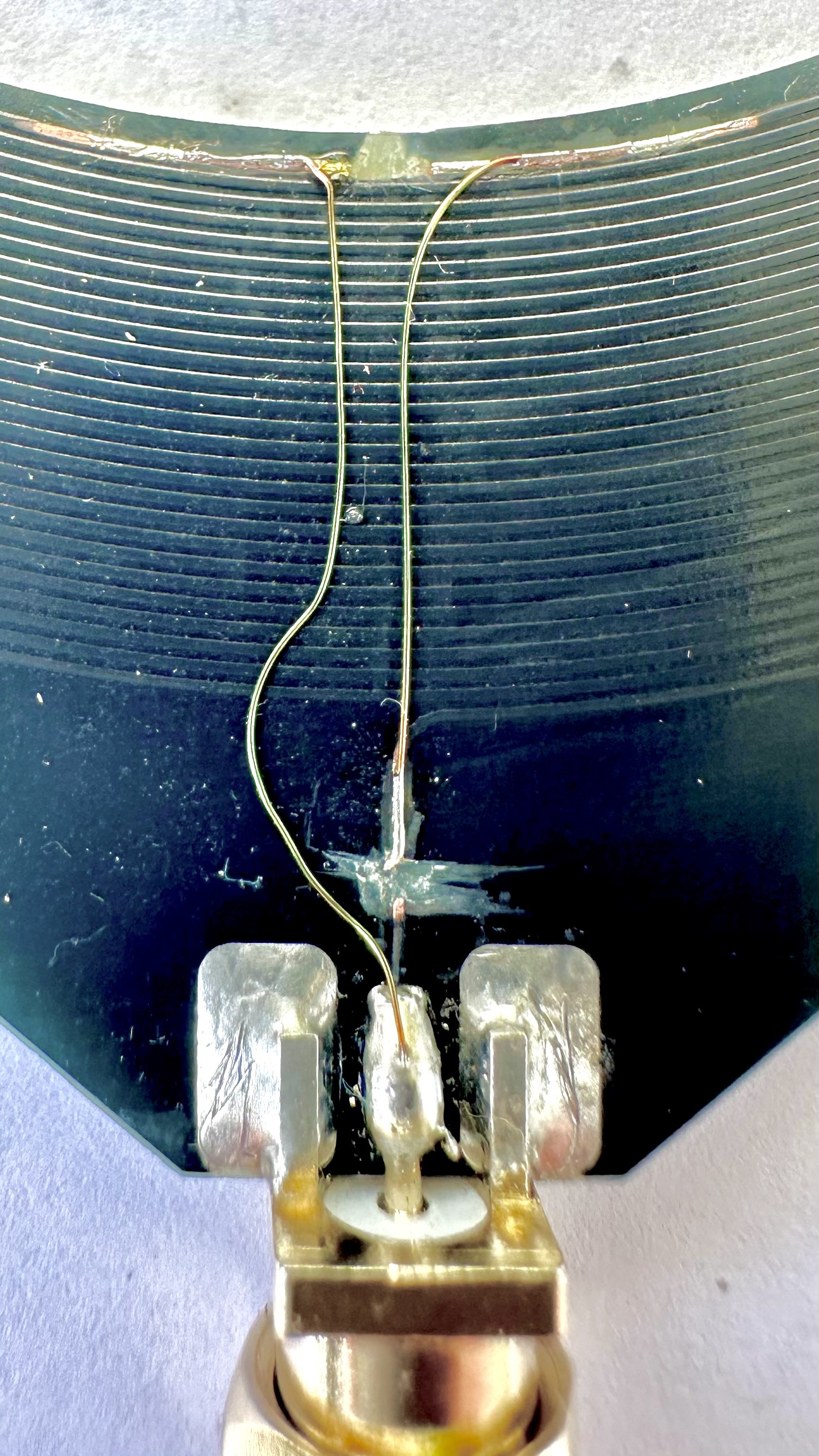
The original „donut“ loop antenna did not work seemingly due to a design issue. A scalpel, two tiny wires, and four solder joints rescued it.
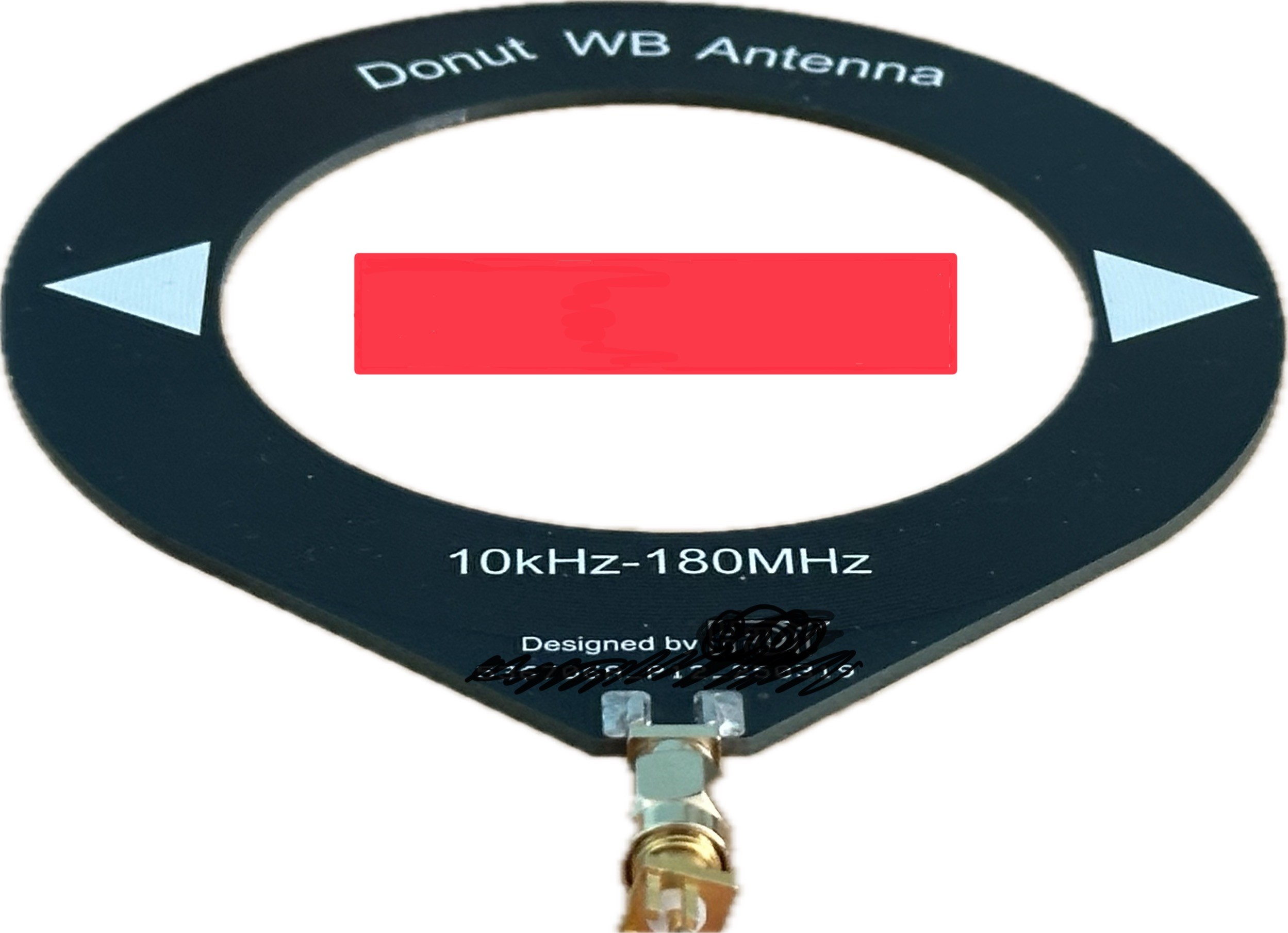
My new DSP/SDR-Rx ATS-Mini arrived with a telescopic antenna and a “Donut WB Antenna (10 kHz – 180 MHz)”. While the receiver works well with the whip antenna, the loop antenna failed to perform. The advertised bandwidth already seemed suspicious during initial inspection.
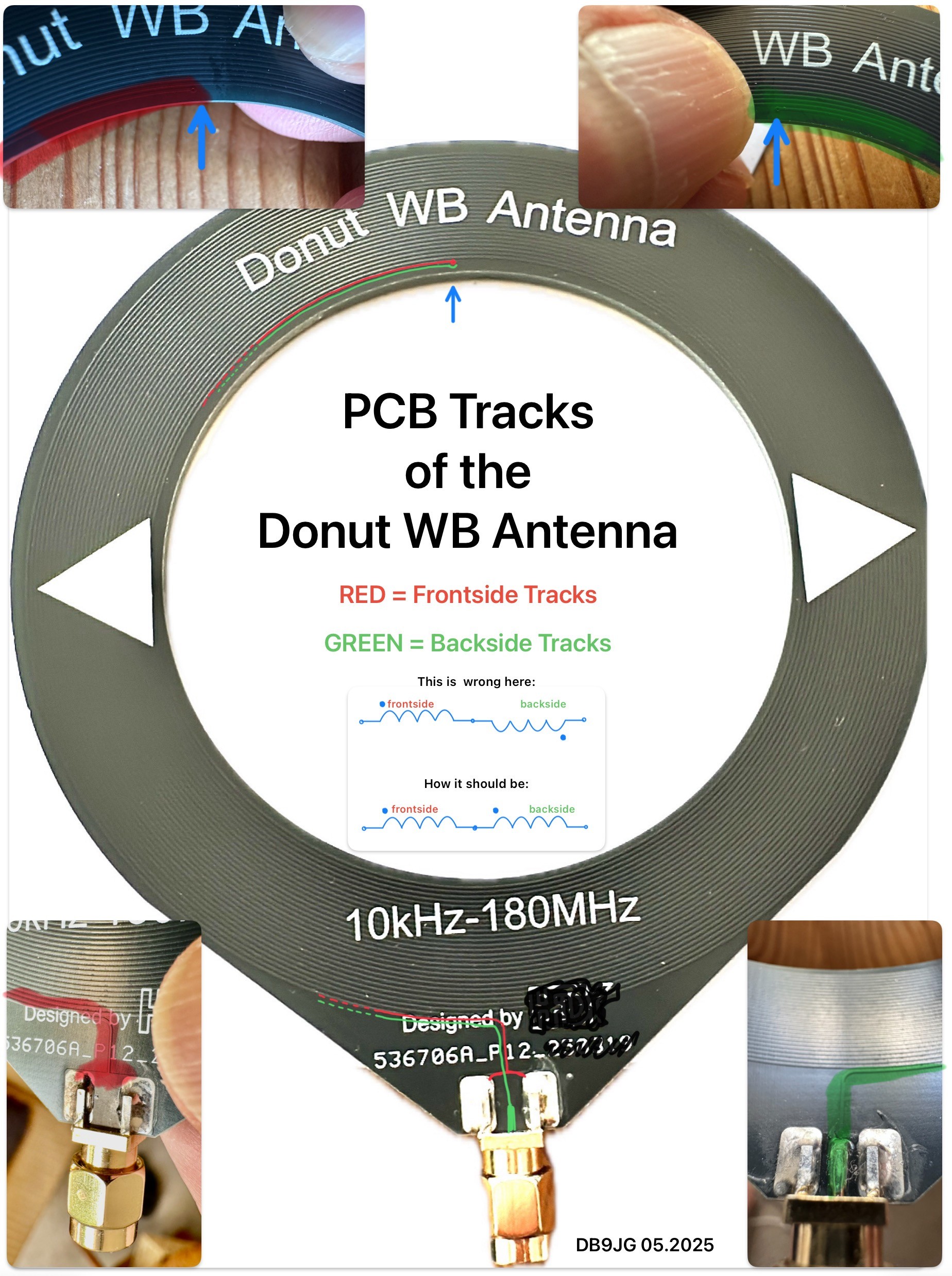
I traced the PCB layout: • From the SMA plug’s ground, the printed coil runs to a via • On the opposite side, it coils again to the SMA center contact After rotating the board 100 times for verification, I confirmed: The printed coils are connected in anti-series – their magnetically induced voltages cancel each other! THIS ANTENNA CAN NOT WORK PROPERLY!!
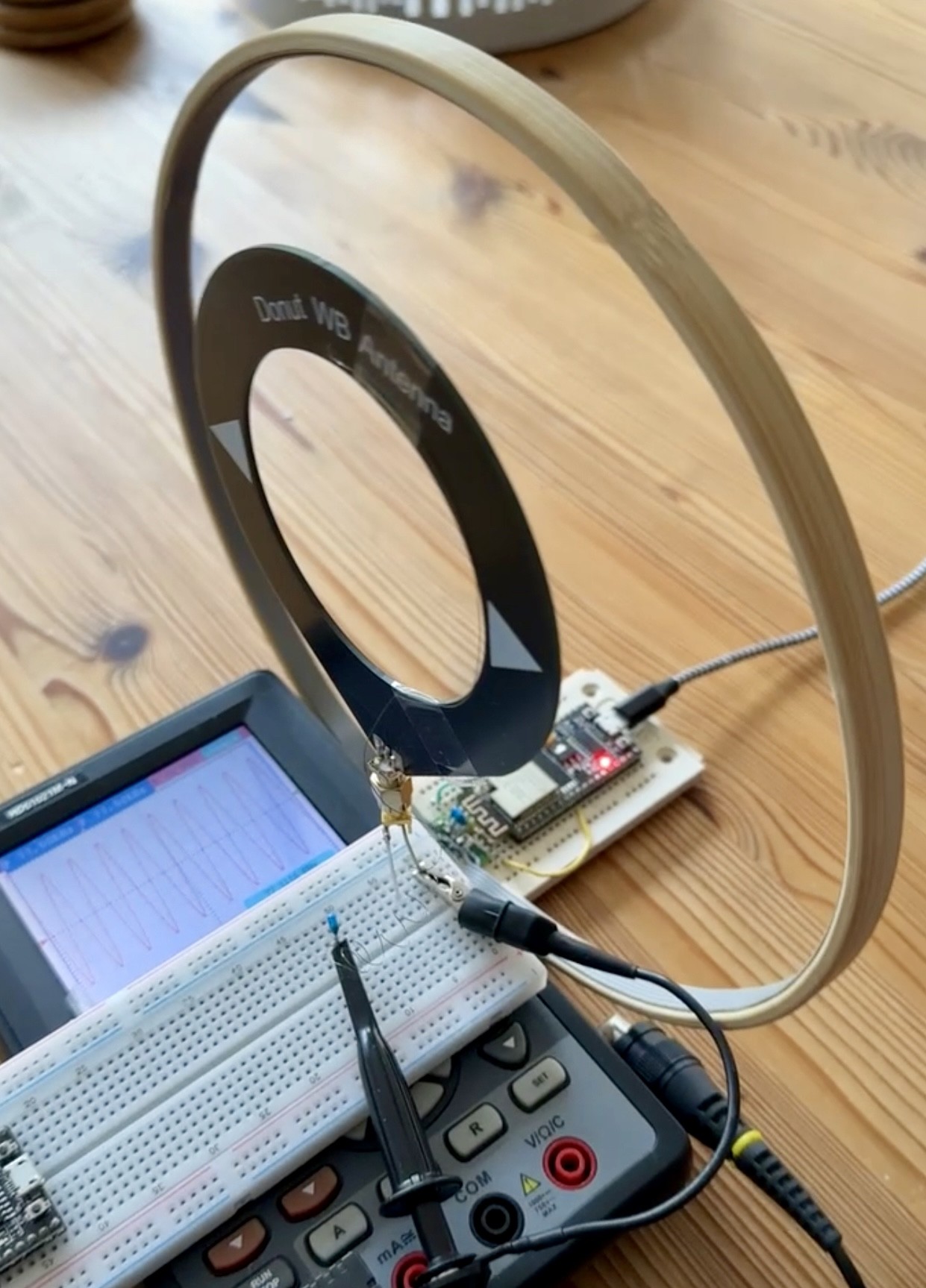
Test procedure: 1. Added a third test point at the hypothetical midpoint connection 2. Used a 77.5 kHz DCF77 signal generator with a magnetic loop as the primary antenna 3. Oscilloscope showed strong signals at both half-coils but zero voltage at the SMA output. This confirmed the anti-series configuration!
Modification: 1. Removed the protective varnish with a scalpel at two locations. 2. Cut the original traces to isolate the ends of the second coil. 3. Reconnected the coil ends with short wires to eliminate the anti-series configuration.
The new configuration now with two coils in series:
Trade-off: One half-winding now runs forward and backward, neutralizing its contribution. But that wireing method seems the best regarding chances of good reproduction :-)
However, in my 77.5 kHz test scenario, the amplitude doubled as predicted.
This antenna can now, for the first time, effectively capture magnetically induced signals across longwave to shortwave bands. The loop may even rival the whip antenna, which functions as a capacitive probe. Nevertheless, it still isn’t a suitable option for the FM band.
EDIT: A test with a VNA showed two not very pronounced parasitic resonace frequencies of the modified loop. One at 10MHz, one at 32MHz


Commenti (3 commenti)