Universal Fuse Distribution Board with Status Indicators
Troubleshooting electrical systems often begins with a simple question: Which fuse has failed? This compact seven-channel fuse distribution board provides immediate visual feedback for every protected output. Unlike conventional fuse indicators that use simple resistor-driven LEDs, each status LED is powered by an LM317 constant-current source, ensuring nearly identical brightness over a wide voltage range. The board supports both DC and AC operation.
Many electronic systems require multiple individually protected power outputs. The usual solution is straightforward: a fuse for each output and perhaps an LED with a series resistor to indicate the presence of voltage.
While this approach is inexpensive, it has one significant disadvantage. The LED brightness depends directly on the supply voltage. An indicator that is clearly visible at 24 V may barely illuminate at 5 V, while becoming excessively bright at higher voltages.
The goal of this project was to create a universal fuse distribution board that combines individual circuit protection with clear and reliable status indication. The board should operate over a wide voltage range, support both AC and DC supplies, and allow service personnel to identify a failed fuse immediately without the need for additional test equipment.
Design Overview
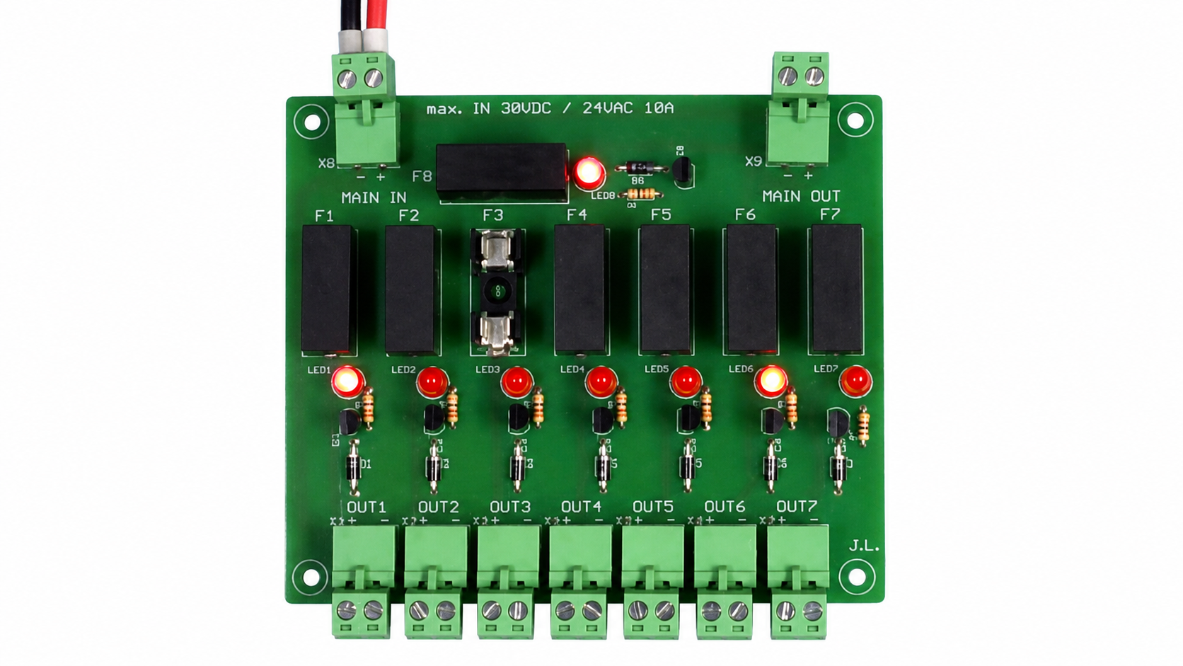
The circuit board features seven individually fused output channels and an additional main fuse.
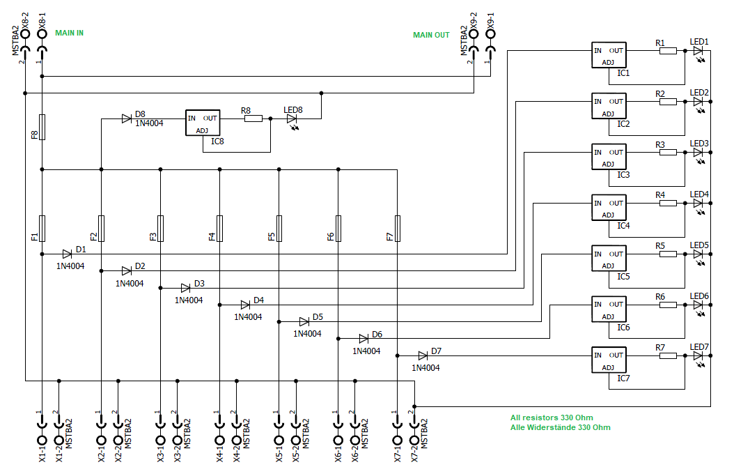
Each channel consists of:
Fuse protection
Indicator rectifier/protection diode
LM317 constant-current source
Status LED
The LED monitoring circuit is connected after the fuse. Therefore, the LED indicates the actual condition of the protected output. If a fuse opens, the corresponding LED immediately turns off, allowing the faulty channel to be identified at a glance.
This arrangement avoids a common problem found in some monitoring circuits where the indicator only confirms the presence of input voltage rather than the status of the protected output itself.
Constant-Brightness LED Indicators
The most distinctive feature of the design is the use of an LM317 configured as a constant-current source for each status LED.
In conventional designs, a simple resistor limits the LED current. As the supply voltage changes, the LED current changes as well, resulting in noticeable brightness variations.
By operating the LM317 as a constant-current source, the LED current remains nearly constant across a wide input voltage range. As a result, all status indicators maintain a uniform appearance whether the board is powered from low-voltage control circuits or higher-voltage industrial supplies.
This makes fault identification easier and provides a more consistent visual indication compared with conventional resistor-driven indicators.
AC and DC Compatibility
During development, an additional requirement emerged: the board should not only support DC supplies but also common 24-VAC control transformers frequently found in industrial environments.
To achieve this, a diode is placed in front of each indicator circuit. This diode performs several functions simultaneously:
Rectification for AC operation
Reverse-polarity protection for the LED
Protection of the LM317 current source
Because the LM317 and LED always receive the correct polarity, the same board can be used with both AC and DC supplies without modification.
The design is suitable for DC operation from approximately 5 V to 30 V. It can also be used with 24 VAC supplies. After rectification, the resulting peak voltage remains within the operating limits of the LM317, allowing a single design to cover a broad range of practical applications.
Practical Advantages
The board offers several advantages in everyday use:
Immediate identification of blown fuses
Constant LED brightness over a wide voltage range
Individual protection for seven output channels
Additional protection of the incoming supply
Support for both AC and DC systems
Simple installation and maintenance
Clear visual diagnostics without measurement equipment
These features make the board useful not only for industrial control systems but also for laboratory equipment, educational projects, automation systems, and custom electronics installations.
Future
Future versions could incorporate optocouplers connected in series with the status LEDs. This would allow galvanically isolated monitoring of each fused output by a control system such as an O-M-S-U input module. The additional LED forward voltage would slightly increase the minimum operating voltage but would be of little concern in typical 12-V and 24-V applications.
Conclusion
Although fuse distribution boards are common components in many systems, small improvements can significantly increase their usefulness. By combining conventional fuse protection with LM317-based constant-current indicators, this design provides clear and consistent visual feedback independent of the supply voltage.
The additional ability to operate from both AC and DC sources further increases the flexibility of the design. The result is a practical and service-friendly fuse distribution board that simplifies troubleshooting and improves system diagnostics.


Commenti (0 commenti)